
Laser written waveguide polarization swapper

Inactive Publication Date: 2005-03-08
NEOPHOTONICS CORP
View PDF11 Cites 21 Cited by
  • Summary
  • Abstract
  • Description
  • Claims
  • Application Information

AI Technical Summary

Benefits of technology

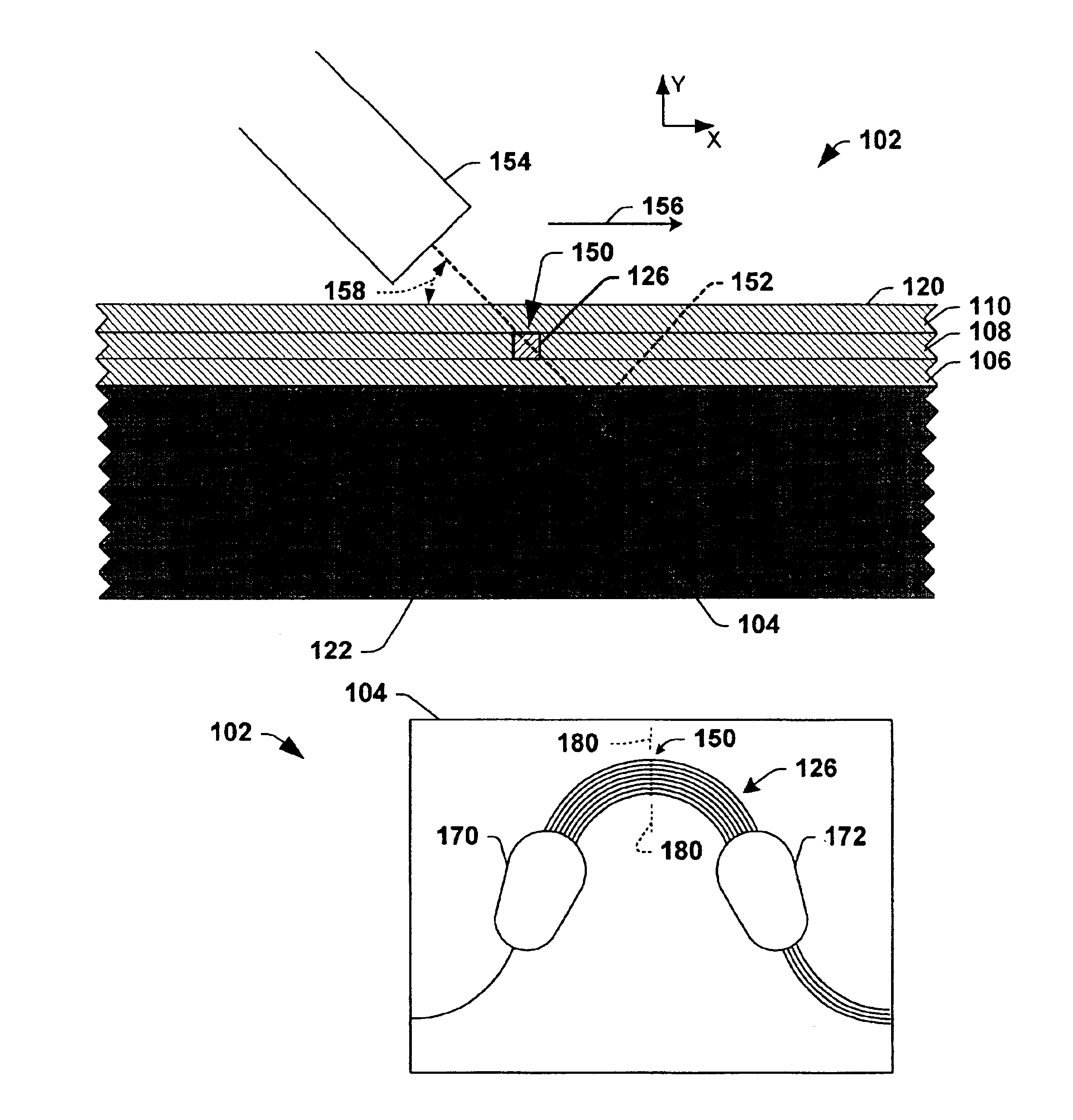
The present invention provides optical integrated circuits (OICs), in which a polarization swapping portion or waveplate is formed in a portion of a waveguide using polarized light, for example, from a laser. The invention further comprises methods for fabricating OICs and for mitigating polarization dependence in OICs. The invention may thus be employed to mitigate the polarization dependence in OICs such as arrayed waveguide gratings (AWGs), while avoiding or reducing the manufacturing difficulties associated with forming a slot and installing a separate waveplate into such devices. Moreover, the polarization swapping performance of the waveguide can be easily monitored and / or adjusted during formation.
The polarization swapping portion of the waveguide can be polarized at an angle of about 42 degrees or more and about 48 degrees or less, for example, about 45 degrees with respect to axes perpendicular to the axis of the optical path by irradiating the polarization swapping portion with polarized light at an appropriate angle, so as to mitigate polarization dependence in the waveguide. The polarized light can be fempto-second pulsed visible light, ultra-violet (UV) light, or other light. The polarization swapping portion can be formed in the waveguide using polarized light from a laser or other source, and additionally, a prism may be employed in order to provide the polarized light at an appropriate angle with respect to the waveguide.

Problems solved by technology

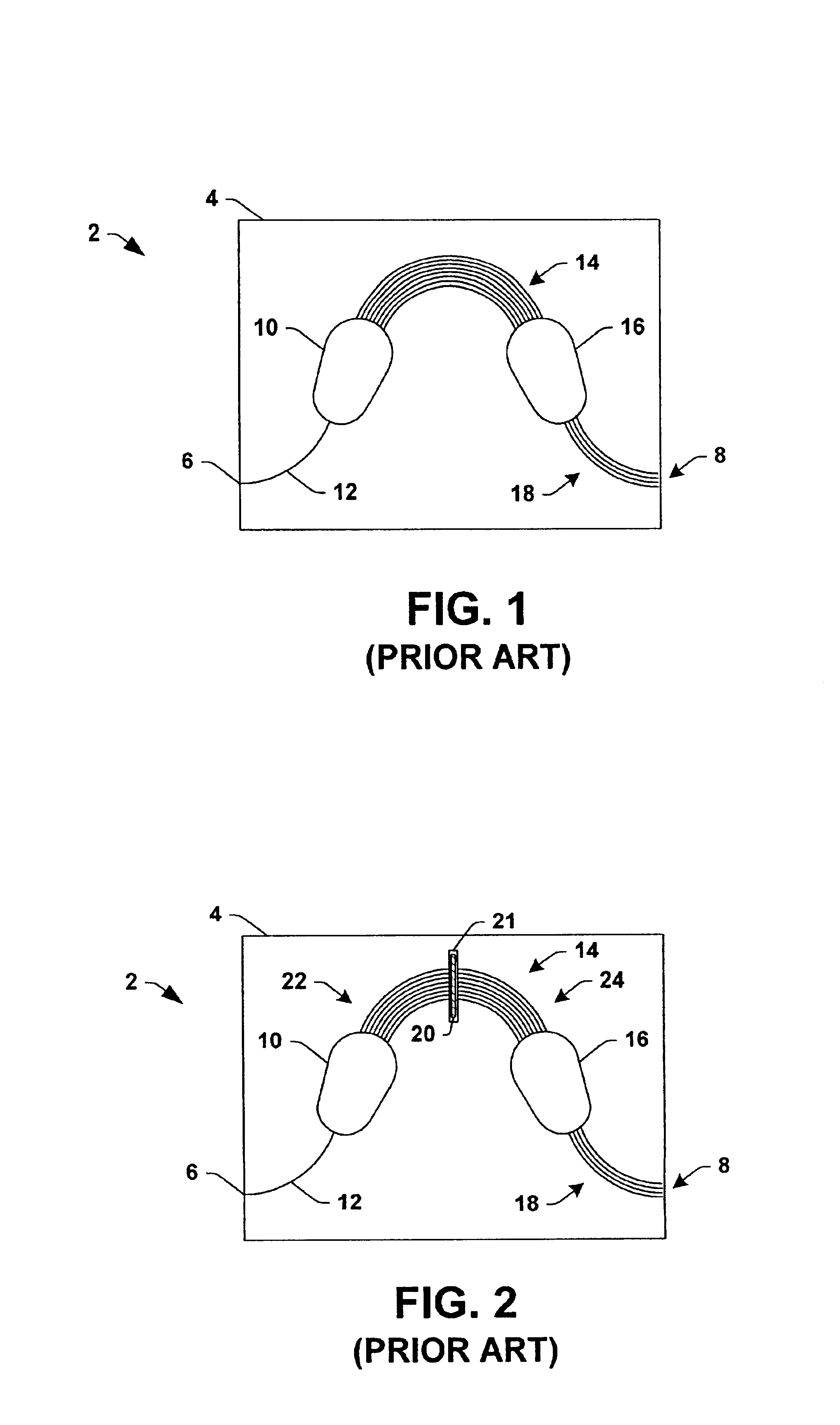
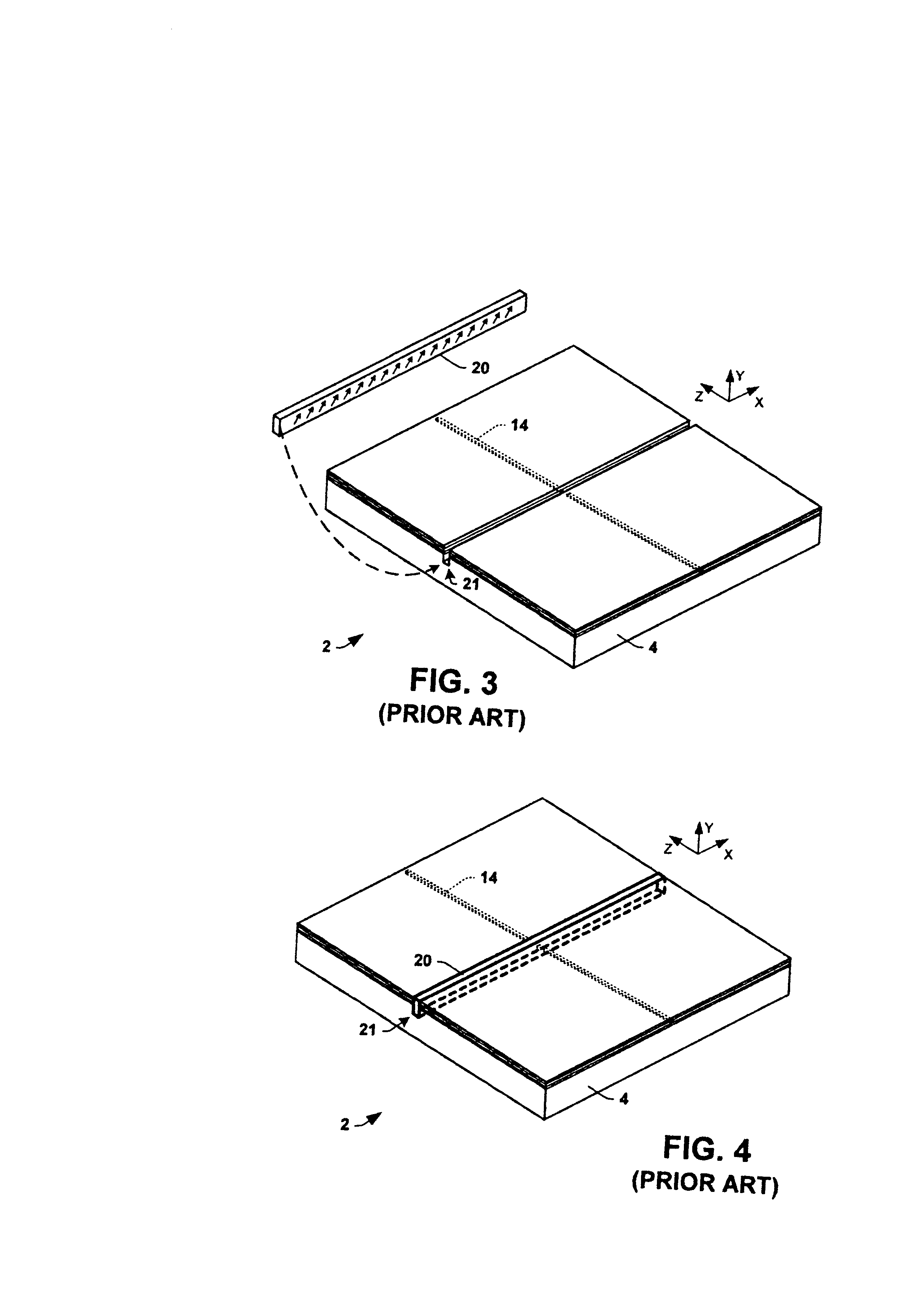
Moreover, it is difficult to monitor and / or adjust or tune the polarization swapping performance of the installed waveplate 20 in the slot during manufacturing.

Method used


Image

  • Laser written waveguide polarization swapper
  • Laser written waveguide polarization swapper
  • Laser written waveguide polarization swapper

Examples


Embodiment Construction

The various aspects of the present invention will now be described with reference to the drawings, wherein like reference numerals are used to refer to like elements throughout. The invention provides optical integrated circuits (OICs) having waveguides with a polarization swapping portions formed therein using polarized light, for example, from a laser. The invention further comprises methods for fabricating OICs and for mitigating polarization dependence in OICs. The invention may thus be employed in association with any type of OIC, such as arrayed waveguide gratings (AWGs), while avoiding or reducing the manufacturing difficulties associated with forming a slot and installing a separate waveplate into such devices. Moreover, the polarization swapping performance of the waveguide can be easily monitored and / or adjusted during formation.

One implementation of the invention is illustrated and described hereinafter with respect to a planar lightwave circuit (PLC) 102 of FIGS. 5-10. A...


PUM

PropertyMeasurementUnit
Angleaaaaaaaaaa
Angleaaaaaaaaaa
Angleaaaaaaaaaa

Abstract

Optical integrated circuits are disclosed in which a polarization swapping portion is formed in a portion of a waveguide using polarized light from a laser. Also disclosed are methods for fabricating optical integrated circuits and for mitigating polarization dependence in optical integrated circuits.

Description

TECHNICAL FIELDThe present invention relates to the art of optical integrated circuits and more particularly to apparatus and methods for mitigating polarization dependence in optical integrated circuits.BACKGROUND OF THE INVENTIONOptical integrated circuits (OICs) come in many forms such as 1×N optical splitters, optical switches, wavelength division multiplexers (WDMs), demultiplexers, optical add / drop multiplexers (OADMs), and the like. Such OICs are employed in constructing optical networks in which light signals are transmitted between optical devices for carrying data and other information. For instance, traditional signal exchanges within telecommunications networks and data communications networks using transmission of electrical signals via electrically conductive lines are being replaced with optical fibers and circuits through which optical (e.g., light) signals are transmitted. Such optical signals may carry data or other information through modulation techniques, for tr...

Claims


Application Information

Patent Timeline
IPC IPC(8): G02B6/126G02B6/34
CPCG02B6/12011G02B6/126G02B6/12023
Inventor TICKNOR, ANTHONY J.
Owner NEOPHOTONICS CORP
Learn More