
Compact dynamic crossbar switch by means of planar optics

Inactive Publication Date: 2005-03-08
MIRAGE INNOVATIONS
View PDF8 Cites 58 Cited by
  • Summary
  • Abstract
  • Description
  • Claims
  • Application Information

AI Technical Summary

Benefits of technology

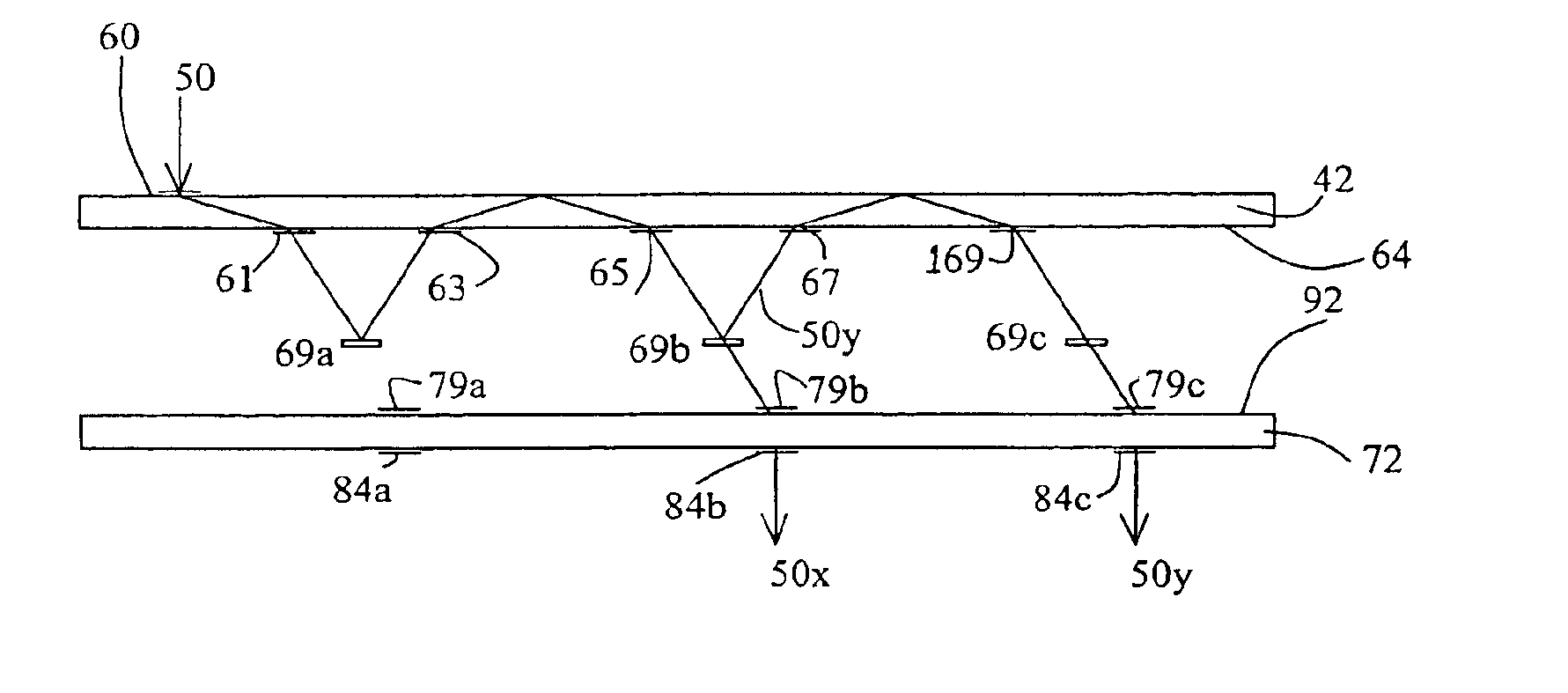
The present invention is an energy-efficient planar optical crossbar switch, and a shutter assembly therefor. Used for routing one or more light sources, the switch has a compactness that is compatible with optoelectronic circuit package sizes. The optical crossbar switch includes two thin planar substrates adapted for the transmission of the light beam ad made of an optical medium such as glass, on each of which is recorded or attached at least two diffractive optical elements. At least one collimated light beam is propagated within each substrate between the diffractive optical elements by means of total internal reflection, or, if the surfaces of the substrate are coated with a reflecting layer, by means of specular reflection. The inventive shutter assembly enables the routing to be performed with substantially no energy loss, in sharp contrast to the system of the prior art.
The present invention successfully addresses the shortcomings of the existing technologies by providing an all-optical switch that is simple and reliable, and that, from an energy standpoint, is significantly more efficient and controlled than the most advanced switches of the prior art.

Problems solved by technology

In addition, the lack of electrical conversion allows for support of bit rates ranging up to 40 Gb / s and higher, beyond the reach of practical optoelectronic systems.
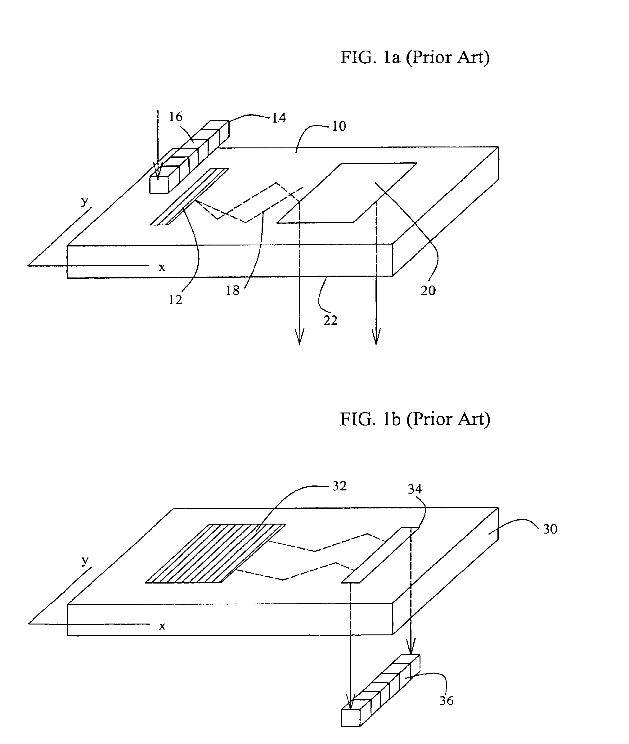
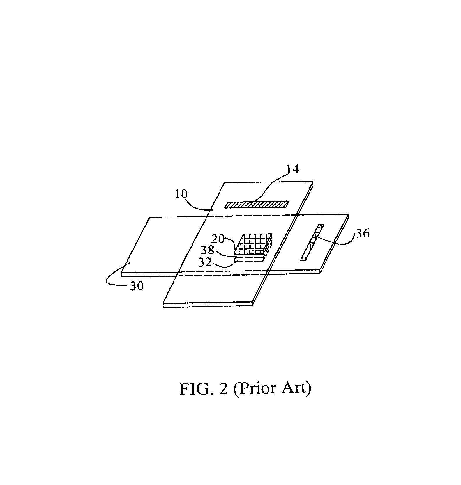
The use of discrete optical components, and the relatively large number thereof required, results in a switch with comparatively high weight and volume.
The alignment accuracy required between individual components is extremely difficult to achieve and often impractical for the high density of channels to be switched.
As a result, free space propagation optical crossbar switching systems are very sensitive and non-robust, have relatively low positioning accuracy and are subject to thermal instability, thus making them unsuitable for general industrial use.
All of these factors combine to make such free space switches incompatible with the small size and circuit construction techniques used in the integrated optoelectronic technology used in modern signal processing and communications systems.
Consequently, despite the advantages inherent in the above-described all-optical switch, the energy inefficiency makes such a switch of very limited practical utility.
The problem is particularly severe for large switching arrays, in which the ratio of light output to light input can easily fall below 0.1.
Furthermore, the light intensity is not uniform across each row of the SLM matrix, mid therefore light output may vary according to the choice of the {i,j} connection.

Method used


Image

  • Compact dynamic crossbar switch by means of planar optics
  • Compact dynamic crossbar switch by means of planar optics
  • Compact dynamic crossbar switch by means of planar optics

Examples


Embodiment Construction

The present invention is an energy-efficient planar optical crossbar switch, and a shutter assembly therefor. The switch has a compactness that is compatible with optoelectronic circuit package sizes. The optical crossbar switch has two thin planar substrates made of an optical medium such as glass, on each of which is recorded or attached at least two diffractive optical elements. The light propagates inside each substrate between the diffractive optical elements by means of total internal reflection, or, if the surfaces of the substrate are coated with a reflecting layer, by means of specular reflection. The inventive shutter assembly enables the routing to be performed with substantially no energy loss, in sharp contrast to the system of the prior art.

It must be emphasized that the planar substrates, as well as any elements disposed therebetween and / or thereon, can be affixed to form a single, sturdy, integral unit.

The principles and operation of the optical crossbar switch accor...


PUM


Abstract

An optical switch including: (a) a light transmissive substrate, and (b) a two-dimensional array, disposed on the light transmissive substrate, the two-dimensional array having rows and columns of reflective shutter assembly elements, each of the reflective shutter assembly elements including: (i) a reflective shutter, and an output diffractive optical element.

Description

FIELD AND BACKGROUND OF THE INVENTIONThe present invention relates to optical switches and, more particularly, to crossbar switching components for optical signal processing, and to methods of improving optical signal processing by means of such crossbar switching components.Although fiberoptic systems have been the backbone of the telecommunications industry, their main use to date has been as point-to-point information pipelines. The switching and processing of signals have been accomplished using electronic devices.Optical cross-connect (OXC) switches are important in optical fiber communications networks, particularly in systems using wavelength division multiplexing (WDM). Optical switches can be divided into two classes, all-optical and optoelectronic. All-optical switches are distinguished by the lack of any electrical conversion of the optical signals being switched. This enables them to be bit rate independent and protocol transparent. In addition, the lack of electrical co...

Claims


Application Information

Patent Timeline
IPC IPC(8): G02B6/35G02B6/34
CPCG02B6/34G02B6/3556G02B6/356G02B6/3512
Inventor NIV, YEHUDADAVID, YAIR
Owner MIRAGE INNOVATIONS
Learn More