Method for decimating seismic traces driven by the seismic path

Inactive Publication Date: 2005-03-08
TOTAL FINA
View PDF11 Cites 88 Cited by
  • Summary
  • Abstract
  • Description
  • Claims
  • Application Information

AI Technical Summary

Benefits of technology

The originality of the method as set forth in the invention resides in the fact that the decimation is no longer performed in a statistical manner, but is based on geophysical criteria. All 3D acquisition traces are sorted based on the seismic path that is defined the source-receiver couple coordinates. Therefore, this pretreatment makes it possible to reduce the volume of 3D seismic data in a simple and efficient manner. Simple because the geophysicist will no longer have to make delicate choices (ch

Problems solved by technology

Efficient, on the one hand because this method makes it possible to rapidly select the supernumerary traces, and on the other hand, because most of all th

Method used


Image

  • Method for decimating seismic traces driven by the seismic path
  • Method for decimating seismic traces driven by the seismic path
  • Method for decimating seismic traces driven by the seismic path

Examples


Embodiment Construction

Basic Concept of the Invention

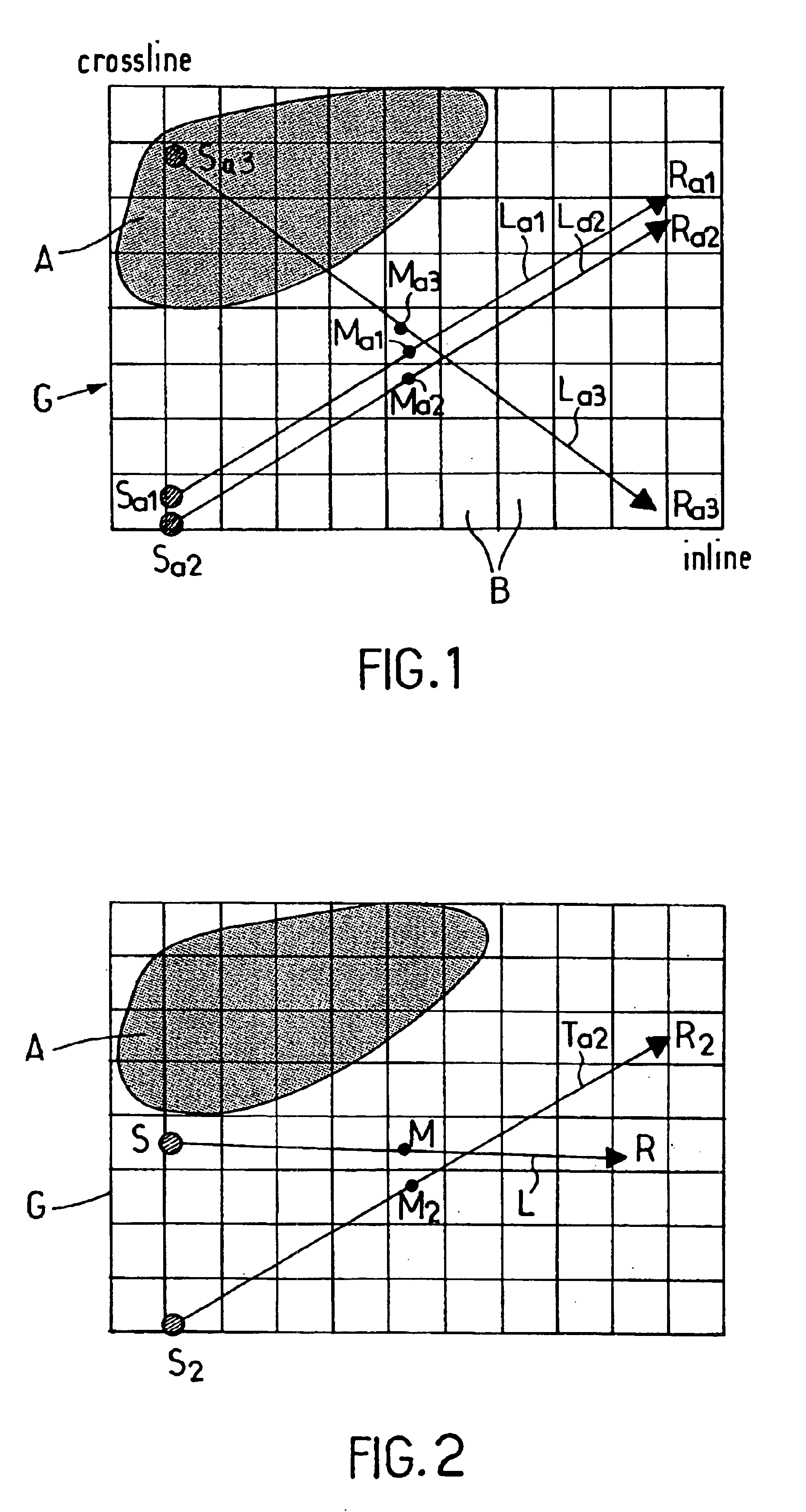
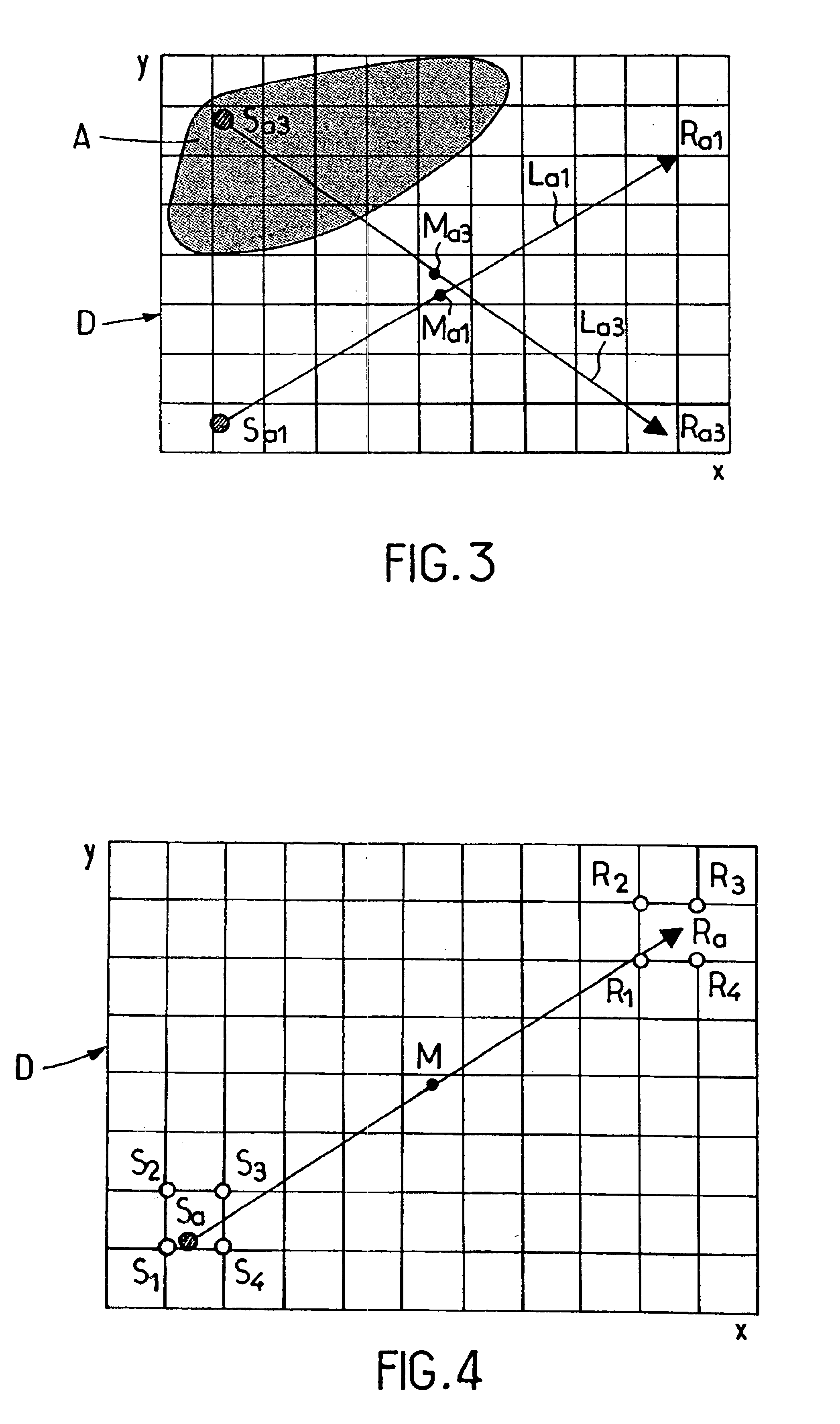
FIGS. 1 and 2 having already been described, we will pass directly on to the description of FIGS. 3 through 6.

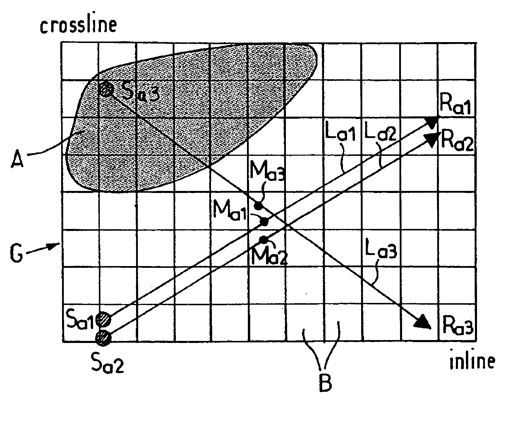
When the complexity of the subsoil is such that a seismic treatment in time becomes inadequate, the notion of mid point no longer makes sense. In a depth seismic treatment, and more precisely in a PSDM treatment, the only indications that must be taken into consideration are the coordinates of the trace sources and receivers. From said coordinates, based on a velocity model, we can recreate the path of the seismic wave and calculate its propagation time.

Starting with the notion that for one given position of a source-receiver couple, there is only one linked seismic path, the applicant realized it would be wise to perform a decimation driven by the seismic paths. This decimation would consist in eliminating all source-transmitter couples whose seismic paths are identical or very similar, except for one.

This phase of the method as set forth in th...


PUM


Abstract

A method for decimating seismic traces in an acquisition of 3D data, recording, for each trace, the corresponding source-receiver couple coordinates (Sa1, Ra1), positioning on a decimation grid (D), divided into cells, the source-receiver couple that corresponds to each trace, regrouping all source-receiver couples into iso-path trace collections, where each collection regroups the traces whose seismic paths are identical or similar, organizing the traces in each iso-path collection, and selecting the first trace in each iso-path collection.

Description

BACKGROUND OF THE INVENTIONThis invention relates to a method for decimating seismic traces in order to provide a 3D depth imagery of the subsoil within an acceptable period of time and at an acceptable cost.FIELD OF THE INVENTIONSeismic reflection consists in propagating a train of compression waves emitted by a source through the subsoil and then recording at the surface, through the use of receivers (hydrophones in underwater applications and geophones in land applications), the signals that are reflected by the interfaces between the various geological beds through which they pass. Each receiver makes a recording, called trace, which is formed by a succession of signals, time-based, that art representative of said geological beds.In order to obtain correct images of a 2D cut, we know we must record:CMP (common mid-points) traces close enough to each other, along one cut, to correctly plot the dip of the beds;enough offset traces to be able to optimize the signal-to-noise ratio a...

Claims


Application Information

Patent Timeline
IPC IPC(8): G01V1/00
CPCG01V1/003
Inventor CHARRON, PATRICK
Owner TOTAL FINA
Why Eureka
Try Eureka