Combustion chamber/venturi configuration and assembly method

a combustion chamber and venturi technology, applied in mechanical equipment, machines/engines, lighting and heating equipment, etc., can solve problems such as tbc erode, and achieve the effects of improving inspection and repair techniques, convenient insertion and removal, and convenient access

Inactive Publication Date: 2005-03-15
H2 IP UK LTD
View PDF6 Cites 18 Cited by
  • Summary
  • Abstract
  • Description
  • Claims
  • Application Information

AI Technical Summary

Benefits of technology

An improved combustion liner configuration is disclosed incorporating a unique assembly methodology for a combustion liner containing a venturi that utilizes venturi cooling air in the combustion process that allows for improved inspection and repair techniques. The combustion liner includes an upper liner, a lower liner, a cap assembly, and a venturi assembly. The cap assembly is fixed to the upper liner at a first upper end and the venturi assembly is inserted into the upper liner from a second upper end. The upper liner with cap assembly and venturi assembly is then inserted into a first lower end of the lower liner. A plurality of pins are inserted through the lower liner, upper liner, and venturi assembly in order to fix the venturi within the combustion liner. Providing the assembly point for the combustion liner proximate the venturi assembly allows for easier insertion and removal of the venturi assembly into the combustion liner as well as easier access to the combustion liner for inspection and repair of the thermal barrier coating.

Problems solved by technology

Over time, exposure to elevated temperatures causes the TBC to erode and therefore necessitates inspection of the combustion liner and repair and replacement of worn liner elements, Including the thermal barrier coating.

Method used


Image

  • Combustion chamber/venturi configuration and assembly method
  • Combustion chamber/venturi configuration and assembly method
  • Combustion chamber/venturi configuration and assembly method

Examples


Embodiment Construction

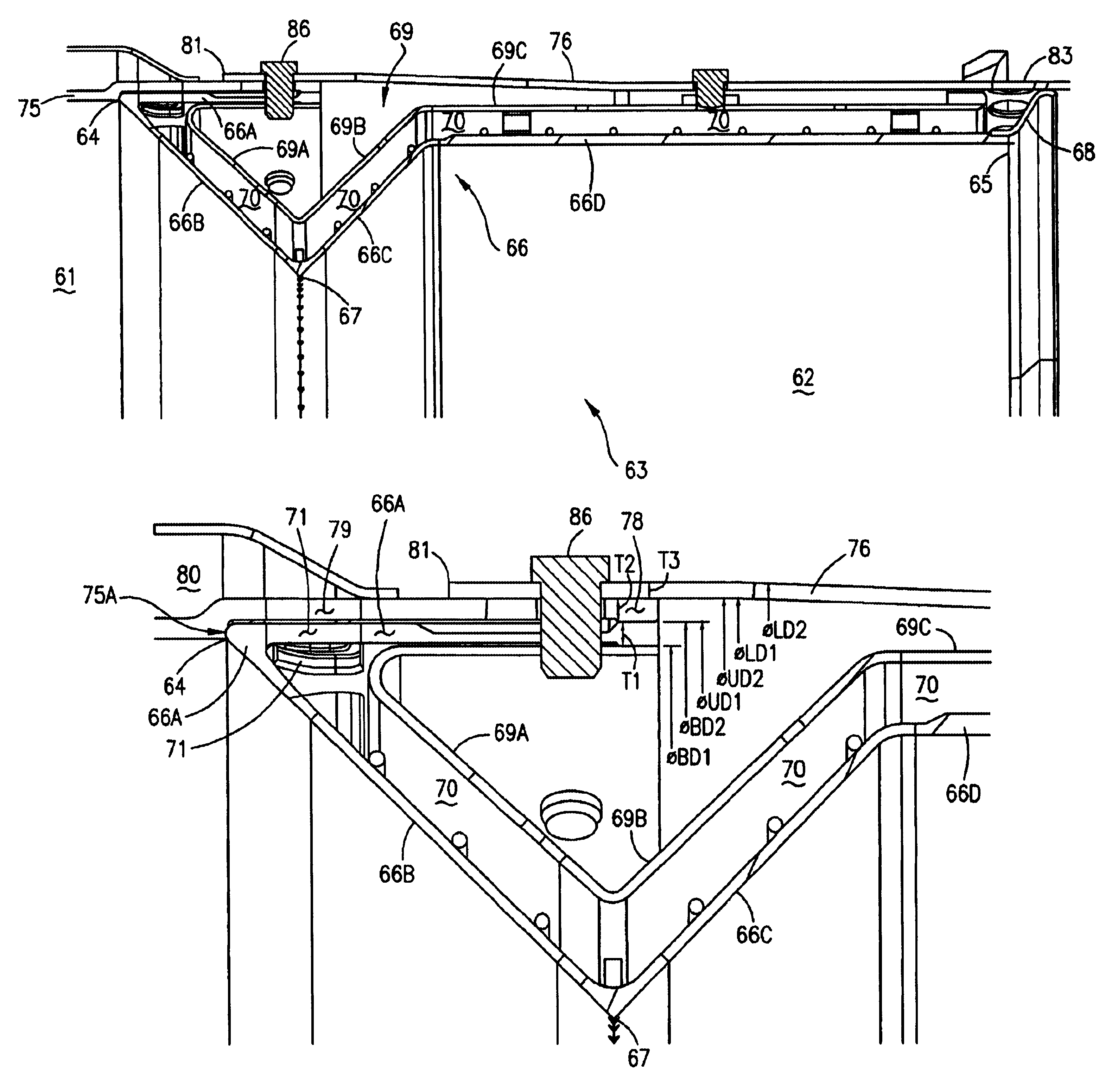
The present invention is shown in detail in FIGS. 3-5. A gas turbine combustor 60 contains a first combustion chamber 61 and a second combustion chamber 62 in fluid communication. Referring to FIG. 4, gas turbine combustor 60 further comprises a venturi assembly 63 having a first venturi end 64 proximate first combustion chamber 61 and a second venturi end 65 proximate second combustion chamber 62. Venturi assembly 63 also contains a flowpath wall 66 extending from first venturi end 64 to second venturi end 65 and having a first outer band 66A, a first convergent wall 66B, a first divergent wall 66C abutting first convergent wall 66B at a first throat 67, which is positioned axially between first combustion chamber 61 and second combustion chamber 62, and a first annular wall 66D extending from first divergent wall 66C. Fixed to first annular wall 66D, proximate second venturi end 65, is a blocking ring 68. Referring now to FIG. 5, first outer band 66A has a first band diameter BD1 ...


PUM


Abstract

A two-stage gas turbine combustor is disclosed that incorporates an improved assembly and disassembly methodology that results in improved inspection and repair techniques. The combustor includes an upper liner, lower liner, cap assembly, and a venturi assembly that directs cooling air into the combustion chamber for use in the combustion process, wherein a venturi assembly is inserted within an upper liner and an upper liner is then inserted in a lower liner. The venturi assembly, upper liner, and lower liner are fixed together with a plurality of easily removable retaining pins. The improved assembly allows for easier inspection and repair of the upper liner, lower liner, and venturi assembly.

Description

BACKGROUND OF THE INVENTIONThis invention relates generally to an apparatus for reducing nitric oxide (NOx) emissions in gas turbine combustion system. More specifically this invention relates to the apparatus and methodology for assembling the reduced NOx combustion system.Combustion liners are commonly used in gas turbine engines to provide a protected environment for compressed air and fuel to mix and react in order to generate the hot gases necessary to drive a turbine. Due to the extreme exposure to elevated temperatures, combustion liners are typically coated with a thermal barrier coating (TBC) to reduce effects of high temperatures on the base metal of the combustion liner. Thermal barrier coating is typically comprised of a metallic bond coat and a ceramic top coat. Over time, exposure to elevated temperatures causes the TBC to erode and therefore necessitates inspection of the combustion liner and repair and replacement of worn liner elements, Including the thermal barrier...

Claims


Application Information

Patent Timeline
Patent Type & Authority Patents(United States)
IPC IPC(8): F23R3/60F23R3/00
CPCF23R3/005F23R3/60F23R2900/00017
Inventor GARRIDO, MIGUELMILLER, SHAWN
Owner H2 IP UK LTD
Why Eureka
Try Eureka