System with an internal combustion engine, a fuel cell and a climate control unit for heating and/or cooling the interior of a motor vehicle and process for the operation thereof

a technology of internal combustion engine and climate control unit, which is applied in the direction of fuel cell applications, fuel cell applications, sustainable buildings, etc., can solve the problems of internal combustion engine heat generation, high engine efficiency, and limited thermal energy available in the heat transfer circui

Inactive Publication Date: 2005-03-15
WEBASTO THERMOSYST INT
View PDF24 Cites 33 Cited by
  • Summary
  • Abstract
  • Description
  • Claims
  • Application Information

AI Technical Summary

Benefits of technology

A primary object of the present invention is to devise a system with an internal combustion engine, a fuel cell and a climate control unit which, both in stationary operation and also when driving, enables an operating mode in which the exhaust heat of the fuel cell is optimally used.
The invention is based, in part, on the finding that, especially for climate control of the sleeping compartment of a commercial vehicle, the energy from the fuel cell can be advantageously used. The fuel cell can be designed to be correspondingly small as a result of the low power consumption. High climate control performance while driving can be made available by other energy sources.

Problems solved by technology

In stationary operation, for example, the compressor of a climate control unit, or also a stereo system, light source and all those energy consumers which are conventionally supplied by the battery in stationary operation are operated via the fuel cell; however this is only possible for a relatively short time due to the limited capacity of the battery.
Moreover, in modern internal combustion engines, there is the problem that the efficiency of the engine is so high that the heat transfer circuit can make available only comparatively little thermal energy for heating of the motor vehicle interior.
The problem here is that the internal combustion engine is heated at the same time.
While this improves the starting properties of the internal combustion engine, it takes a relatively large amount of energy.
Especially in operating situations in which the engine is to be preheated and the interior is to be heated, not only briefly before starting the vehicle but, for example, in trucks with sleeping compartments, where the sleeping compartment must be heated over a long time interval, the heating of the internal combustion engine demands considerable amounts of energy.
Since latent storages occupy a large volume and have a cooling duration which is greatly limited in time, their use is not suited in many cases.
This is because, when using the motor vehicle battery as the energy supplier, the duration of cooling is also greatly limited, there even being the risk that, after completed stationary air conditioning, sufficient battery power for starting is no longer present.
However, of course, this also has the disadvantages that disturbing noise occurs, power consumption is high, and burdensome emissions are formed.
If in any case the air conditioning system is intended for use while driving and also when stopped, there are requirements which can only be met with difficulty at the same time.
Therefore, if a system is designed for stationary air conditioning, a fuel cell is chosen with correspondingly low output and a corresponding compressor; however, this would result in that the air conditioning could be inadequate while driving.
However, even if the fuel cell and the compressor were designed to be large enough, there would still be different requirements with respect to different situations or also with respect to different areas of the vehicle interior, so that for this reason, the problems would not be adequately solved.

Method used


Image

  • System with an internal combustion engine, a fuel cell and a climate control unit for heating and/or cooling the interior of a motor vehicle and process for the operation thereof
  • System with an internal combustion engine, a fuel cell and a climate control unit for heating and/or cooling the interior of a motor vehicle and process for the operation thereof
  • System with an internal combustion engine, a fuel cell and a climate control unit for heating and/or cooling the interior of a motor vehicle and process for the operation thereof

Examples


Embodiment Construction

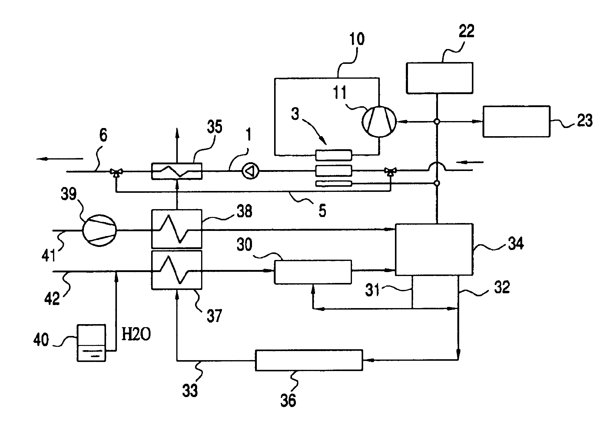
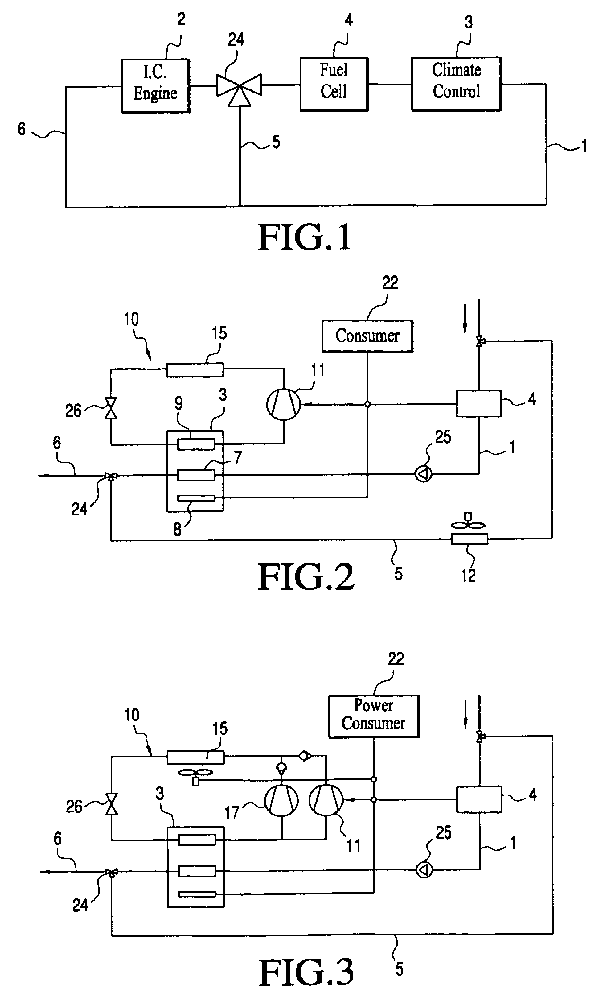
FIG. 1 shows a system in accordance with the invention in a simple schematic. While driving, a climate control unit 3, a PEM fuel cell 4 and an internal combustion engine 2 are joined together in a heat transfer circuit 1. Both the heat produced in the internal combustion engine 2 and also the heat produced in the fuel cell 4 are transported via the heat transfer circuit 1 to the climate control unit 3 which can use the heat for heating of the vehicle interior via a suitable heat exchanger. Between the fuel cell 4 and the internal combustion engine 2, there is a 3-way valve 24 which is designed to interrupt the connection between the fuel cell 4 and the internal combustion engine 2 in the heat transfer circuit 1 and instead to bridge the segment 6 of the heat transfer circuit 1 which runs through the internal combustion engine 2 by a bypass line 5. The coolant is circulated therefore in the resulting isolated circuit only through the fuel cell 4 and the climate control unit 3. A pum...


PUM


Abstract

A system with an internal combustion engine which has a heat transfer circuit, a fuel cell and a climate control unit which is accommodated in the heat transfer circuit of the internal combustion engine. The system has a heat transfer arrangement for transferring the exhaust heat of the fuel cell to the heat transfer circuit and a bypass for bridging a segment of the heat transfer circuit which runs through the internal combustion engine so that, in the bypassed operating state, an isolated circuit is formed. In stationary operation, this enables an optimized operating mode since the internal combustion engine is no longer heated and the exhaust heat of the fuel cell is fully available for heating purposes. The climate control unit can have a fuel cell and an arrangement for transferring the heat produced by the fuel cell to the vehicle interior has a fan unit by which an air flow can be produced for cooling the fuel cell and a heating unit which is powered by the fuel cell and by which the air flow for heating the vehicle interior can be additionally heated. For cooling or heating the interior of a motor vehicle, the system can have a cooling circuit with a compressor, a condenser, an expansion element, and a first evaporator and an APU or a fuel cell to electrically power the compressor, and a second cooling circuit a second evaporator, the second cooling circuit being connected to the first cooling circuit.

Description

BACKGROUND OF THE INVENTION1. Field of the InventionThe invention relates to a system with an internal combustion engine which has a heat transfer circuit, with a fuel cell and with a climate control unit which is accommodated in the heat transfer circuit of the internal combustion engine for heating and / or cooling of the interior of a motor vehicle, as well as to a process for operating such systems.2. Description of Related ArtSystems of the type to which the invention is directed are used if a fuel cell is to be available as an additional energy source. The fuel cell is used, first of all, to produce electrical energy with which the various assemblies of the motor vehicle are supplied. In the reaction which takes place in the fuel cell, heat is released which must be dissipated so that the temperature of the fuel cell does not exceed an allowable upper boundary. Here, it is conventional to provide a separate heat transfer circuit for the fuel cell since the fuel cell is made as a...

Claims


Application Information

Patent Timeline
Patent Type & Authority Patents(United States)
IPC IPC(8): B60H1/32B60H1/00
CPCB60H1/00428B60H1/143B60H1/3222B60H1/323F25B27/00H01M8/04014B60H1/03Y02B90/16F25B5/02F25B2327/001F25B2400/075H01M2250/20H01M2250/405Y02T90/32Y02E60/50Y02B90/10Y02T10/88Y02T90/40
Inventor HORN, OLIVERKHELIFA, NOUREDDINEKOLB, ALEXANDER
Owner WEBASTO THERMOSYST INT
Why Eureka
Try Eureka