Electrical fire extinguishing system

a fire extinguishing system and electric technology, applied in fire rescue and other directions, can solve the problems of not being able to stop the fire where it begins, the prior art device is not designed to stop the fire, and many modern buildings are not of the type, so as to improve the fire extinguishing capability, reduce damage to room furnishings, and improve fire fighting capability.

Inactive Publication Date: 2005-03-15
BOYCE LENUEL +1
View PDF6 Cites 12 Cited by
  • Summary
  • Abstract
  • Description
  • Claims
  • Application Information

AI Technical Summary

Benefits of technology

The electrical fire extinguishing system of the present invention thus provides many features which improve fire fighting capabilities in buildings and structures. For example, because the present invention sends fire suppression fluid directly to the ignition location of the fire, fires are extinguished much more quickly than is possible with other fire fighting devices found in the prior art. Furthermore, because the fire suppression fluid is distributed within the electrical outlets, switches and fixtures of the building, damage to room furnishings is greatly reduced without sacrificing fire fighting efficiency. Finally, as there is currently no method or system in place by which a centralized system can distribute fire suppression fluid directly to electrical outlets and fixtures, it would appear that the present invention addresses and solves a long-felt and unsolved need. It is thus seen that the electrical fire extinguishing system of the present invention is superior and unique when compared to those systems and methods found in the prior art.

Problems solved by technology

While this type of system has been generally acceptable and has saved numerous lives, there is still the problem that many of the fires caused in modern buildings are not of the type which are easily extinguished by the application of water alone.
These devices, however, share one thing in common with the water sprinkler systems of the prior art and that is that they are designed to flood the entire room with fire suppression fluid to extinguish the fire, causing damage to all furnishings within the room.
While this damage is generally considered an acceptable price to pay to put out the fire, it is considered so only because to date there have been presented no alternative solutions which do not cause damage to the building furnishings.
With few exceptions, the prior art devices are not designed to stop the fire where the fire begins, such as in an electrical outlet or electrical fixture.
Instead, the fire may become quite large before the fire extinguishing systems are engaged, which can result in large amounts of damage to room furnishings even if the fire is extinguished.
Thus there is no centralized system which will send fire extinguishing fluid to each of the other electrical fixtures, outlets, and other electrical devices which are integral to modern buildings.

Method used


Image

  • Electrical fire extinguishing system
  • Electrical fire extinguishing system
  • Electrical fire extinguishing system

Examples


Embodiment Construction

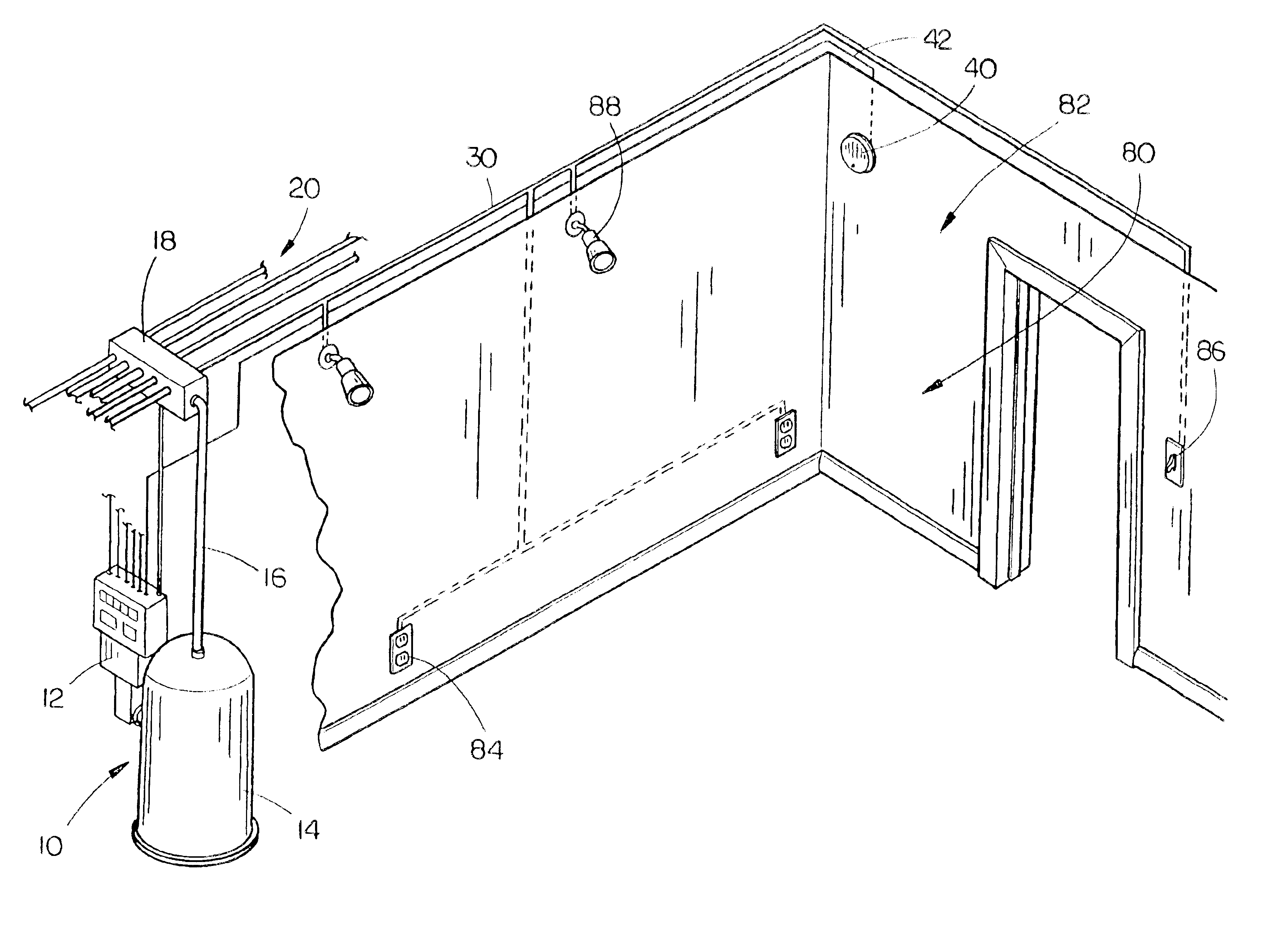
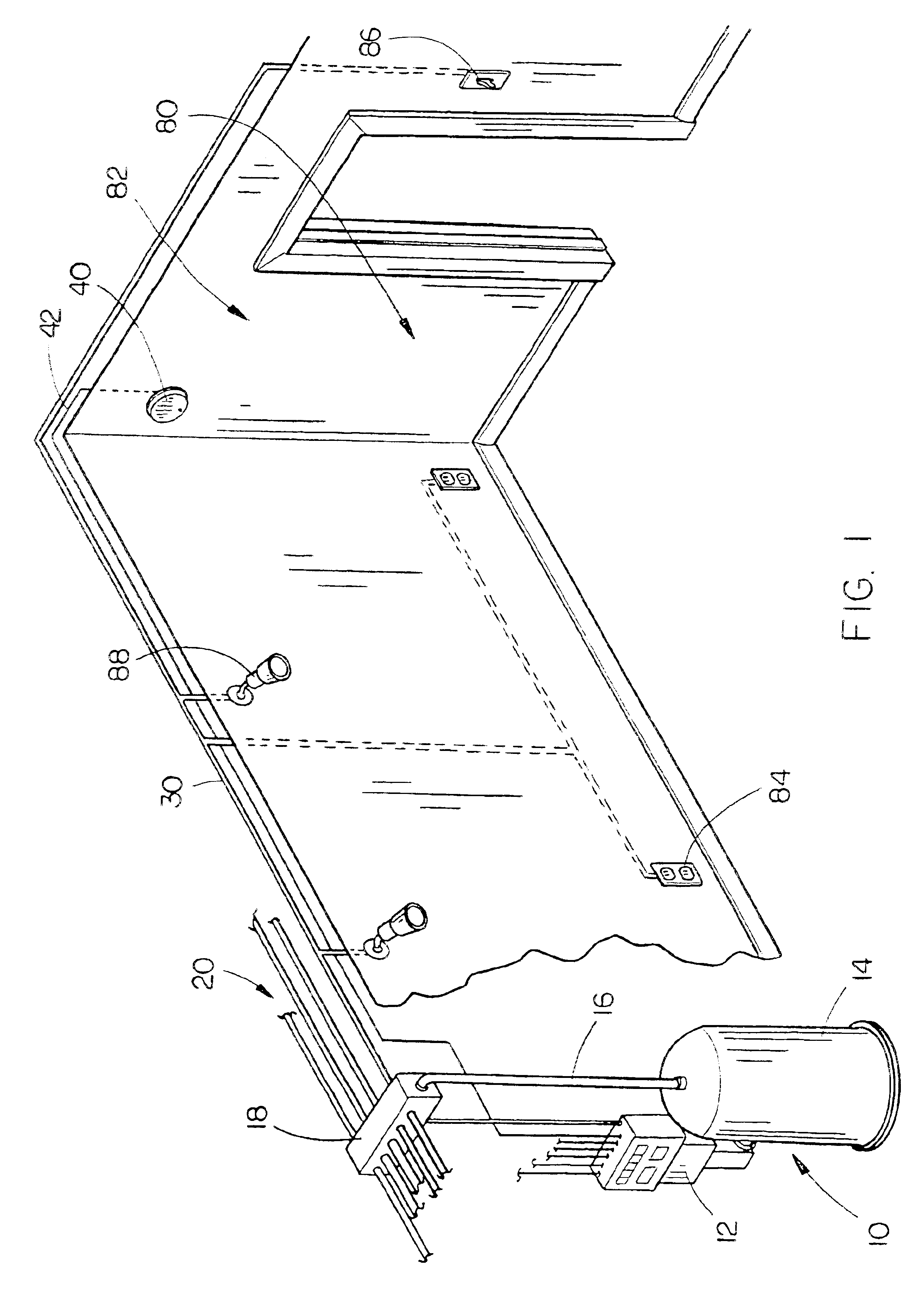
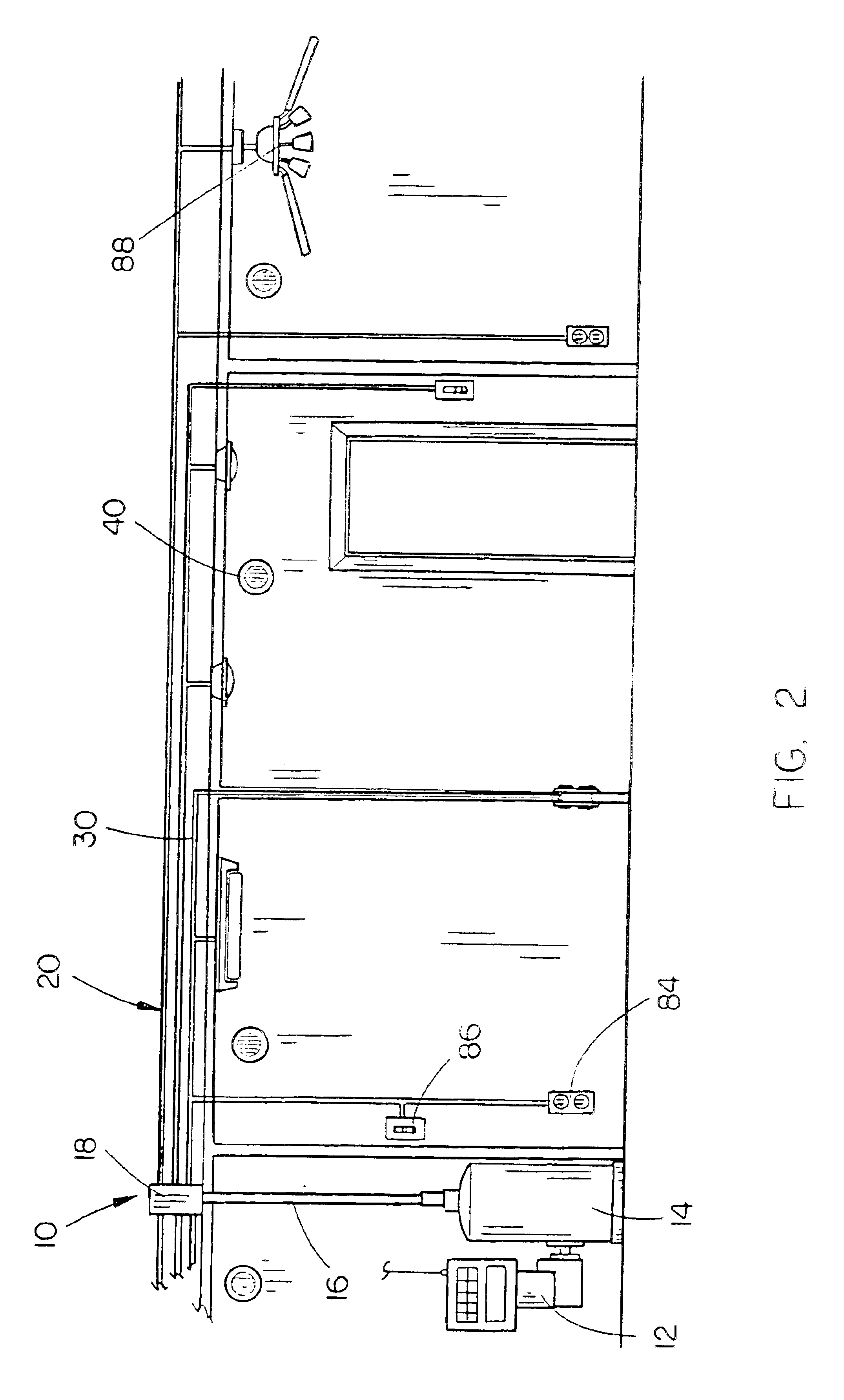
The electrical fire extinguishing 10 of the present invention is shown best in FIGS. 1-3 as including a central computer system 12 and a central fire suppression fluid tank 14 mounted within the building 80 into which the electrical fire extinguishing system 10 of the present invention is fitted. In the preferred embodiment, the central computer system 12 would include at least one micro processor programmed to command the electrical fire extinguishing system 10 of the present invention and the central fire suppression fluid tank 14 would preferably be a pressurized tank holding a large quantity of a fire suppression fluid such as monoammonia phosphate which is liquid in form. Of course, many other different types of fire suppression fluids and solids may be used with the present invention, such as dry chemicals including sodium or potassium bicarbonate or ammonium phosphate, carbon dioxide in either gas or liquid form or Halotron I, which is a specially designed electrical fire sup...


PUM


Abstract

An electrical fire suppression system for a structure having electrical fixtures includes a central computer system and a plurality of fire sensing devices distributed through the structure. A central fire suppression fluid tank is connected to fire suppression fluid pipes and a set of valves are mounted on the fire suppression fluid pipes to control fire suppression fluid flow therethrough, the valves being controlled by the central computer system. Each of the plurality of fire suppression fluid pipes extend into at least one of the electrical fixtures for transfer of fire suppression fluid directly thereto. Upon detection of fire, the fire sensing device signals the central computer system to determine the location of the fire and command the valves on the fire suppression fluid pipes to open to release fire suppression fluid therethrough for extinguishing the fire at the electrical fixture at which it started.

Description

BACKGROUND OF THE INVENTION1. Technical FieldThe present invention relates to fire suppression systems for buildings and, more particularly, to an electrical fire extinguishing system for a structure which includes electrical outlets, devices, appliances and / or fixtures, the system including a central computer system, a plurality of fire sensors distributed through the structure, a central fire suppression fluid tank, a plurality of fire suppression fluid pipes connected to the tank, valves for controlling fluid flow through the fire suppression fluid pipes with each of the fire suppression fluid pipes extending into an associated electrical outlet, device, appliance or fixture, and the central computer system, fire sensing devices and valves cooperating such that upon one of the fire sensing devices detecting fire in the structure, the central computer system signals the appropriate valve to open to release fire suppression fluid into the electrical outlet, device, appliance or fix...

Claims


Application Information

Patent Timeline
Patent Type & Authority Patents(United States)
IPC IPC(8): A62C3/00A62C35/00A62C35/11A62C3/16
CPCA62C35/11A62C3/16
Inventor BOYCE, LENUELLEE, JUDITH A.
Owner BOYCE LENUEL
Why Eureka
Try Eureka