Electrical, fan-cooled tool

a technology of electric power tools and fan cooling, which is applied in the direction of portable power tools, manufacturing tools, drilling machines, etc., can solve the problems of unoptimized cooling potential of air streams, reduced limiting temperature, and overheating of link condensators, so as to prevent suction of dust-containing air

Active Publication Date: 2005-03-15
HILTI AG
View PDF10 Cites 84 Cited by
  • Summary
  • Abstract
  • Description
  • Claims
  • Application Information

AI Technical Summary

Benefits of technology

[0014]Advantageously, the inlet opening(s) is/are arranged in the region of the han...

Problems solved by technology

The losses associated with the storage lead to heating of the link condensator which has, in comparison with the inverted rectifier and the electrical motor, a lower limiting temperature.
As a result, the cooling poten...

Method used


Image

  • Electrical, fan-cooled tool
  • Electrical, fan-cooled tool

Examples


Embodiment Construction

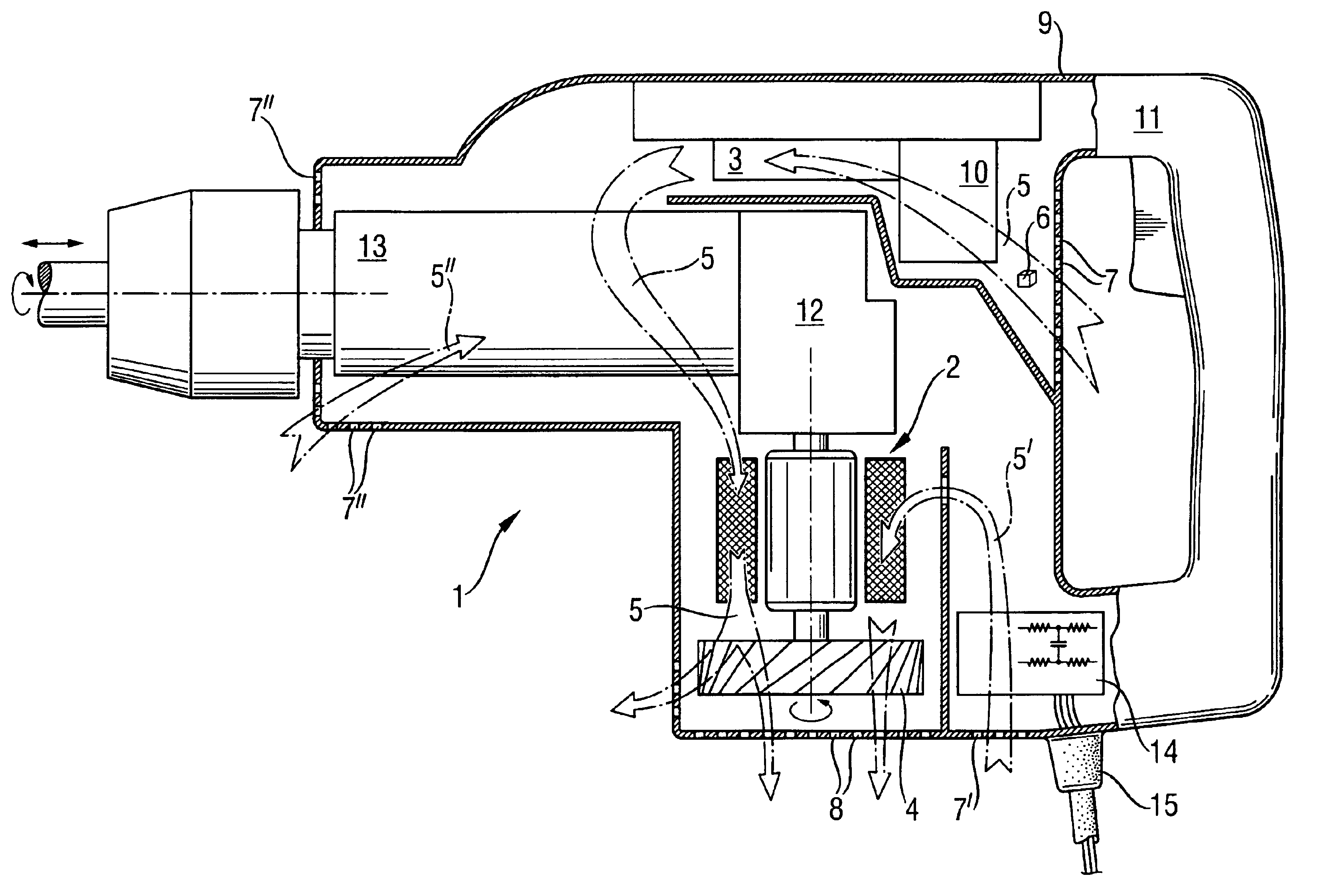
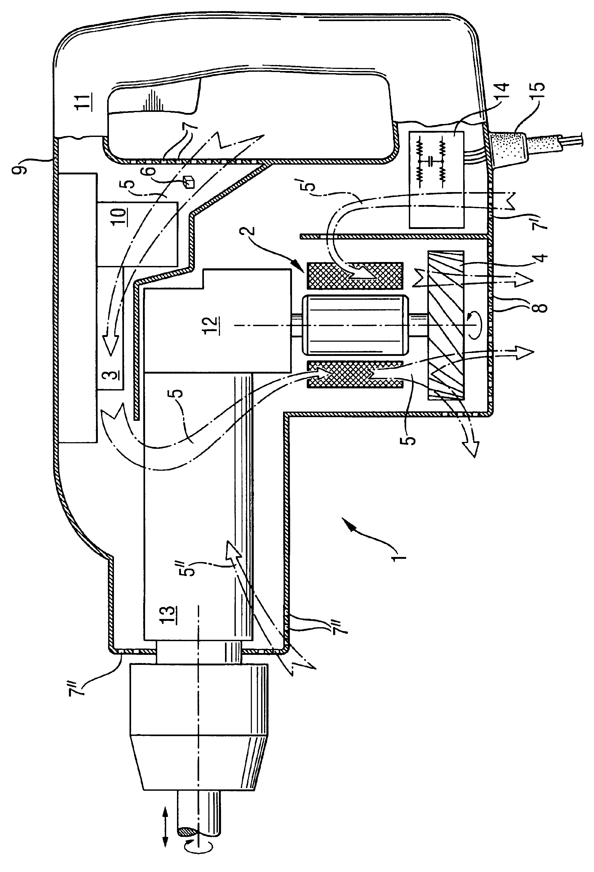
[0019]The present invention will be described with reference to a hammer drill which is shown in the drawing. The hammer drill 1 includes a brushless electrical motor 2 and an inverted rectifier 3 which are arranged in the housing 9 between the at least one inlet openings 7 and outlet openings 8 in an air stream 5 of a volume 6 that is generated by a fan 4. The inverted rectifier 3 is arranged in the air stream 5 in the flow direction downstream of a link condensator 10 and upstream of the electric motor 2. The fan 4 is arranged in the flow direction downstream of the electric motor 2 and in front of outlet openings 8. The inlet openings 7 are provided in the inner region of a handle 11. In the air stream 5 in the flow direction, between the inverted rectifier 3 and the electric motor 2, a gear unit 12 and a percussion mechanism 13 are arranged. A network connection unit 14 is arranged in a parallel air stream 5′ between the inlet openings 7′ and the outlet openings 8. The network c...


PUM

PropertyMeasurementUnit
Volumeaaaaaaaaaa

Abstract

An electrical tool includes a housing having inlet (7) and outlet (8) openings, a brushless electric motor (2) and an inverted rectifier (3) both arranged in the housing (9) between inlet (7) and outlet (8) openings in an air stream (5) of an air volume (6), and a link condensator (10) located in the housing (9) in the air stream (5), with the inverted rectifier (3) being arranged, in the air flow direction, downstream of the link condensator (10) and upstream of the electric motor (2).

Description

BACKGROUND OF THE INVENTION[0002]1. Field of the Invention[0003]The present invention relates to an electrical, fan-cooled, in particular, hand-held tool.[0004]2. Description of the Prior Art[0005]In powerful electrical tools, in particular, in electrical hand-held tools instead of universal motors, brushless electrical motors are used and which include an inverted rectifier and a constant voltage d.c. link with a link condensator for an intermediate power storage. The losses associated with the storage lead to heating of the link condensator which has, in comparison with the inverted rectifier and the electrical motor, a lower limiting temperature.[0006]U.S. Pat. No. 6,127,751 discloses a hand-held power tool in which both the electrical motor and the motor electronics are arranged parallel to each other in an air stream of a fan located in the air flow direction downstream of the electric motor and the motor electronics.[0007]German Publication DE-100 21 356 discloses cooled brush...

Claims


Application Information

Patent Timeline
IPC IPC(8): B25D17/20B25F5/00H02K7/14H02K9/06H02K11/00H02K11/02H02K11/04
CPCB25D17/20B25D2216/0023B25D2250/095B25F5/008H02K7/145H02K9/06H02K11/33H02K11/05H02K11/02H02K11/026H02K11/028
Inventor PFISTERER, HANS-JÜRGENCECCHIN, HOLGERWISSMACH, WALTERKINK, CHRISTOPHKRISTEN, FERDINANDBAUER, RUDOLFMANSCHITZ, ERWIN
Owner HILTI AG
Why Eureka
Try Eureka