Cup caddy for liquid dispensers

a dispenser and cup technology, applied in the field of cups, can solve problems such as unsanitary dispensing conditions, and achieve the effects of convenient and sanitary, safe and more sanitary way of mouthwashing, and saving spa

Inactive Publication Date: 2005-03-15
MEHES PAUL L +1
View PDF20 Cites 22 Cited by
  • Summary
  • Abstract
  • Description
  • Claims
  • Application Information

AI Technical Summary

Benefits of technology

There are many advantages associated with the cup dispenser of the present invention. Dispensing liquids such as mouthwashes, fluoride solutions, medications, and refreshments becomes more convenient and more sanitary using the cup dispenser of the present invention. For example, in an oral care provider's facility, the cup dispenser saves space by not requiring a separate location for cup storage, and provides a safer and more sanitary way to administer mouthwashes and other liquids using disposable cups. Restaurant patrons and office building occupants could benefit from the cup dispenser of the present invention as it provides a convenient and sanitary method of providing courtesy mouthwash in restrooms. The benefits of mouthwash include decreasing the bacteria population in the mouth, leading to fresher breath and healthier teeth and gums. The benefits of mouthwash could be more easily experienced by people in their homes, as using mouthwash would become simpler and more sanitary. Many people who use mouthwash in their homes utilize the cap as a cup, which creates unsanitary dispensing conditions. Disposable cup storage can be problematic in the home, and cup dispenser of the present invention can eliminate the convenience and sanitation concerns with home mouthwash use. The foregoing and other features and advantages of the invention are fully described hereinafter. The accompanying drawings constitute a part of the specification and illustrate an exemplary embodiment of the invention.

Problems solved by technology

Many people who use mouthwash in their homes utilize the cap as a cup, which creates unsanitary dispensing conditions.

Method used


Image

  • Cup caddy for liquid dispensers
  • Cup caddy for liquid dispensers
  • Cup caddy for liquid dispensers

Examples


Embodiment Construction

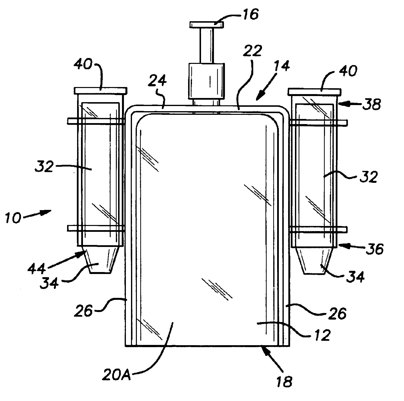
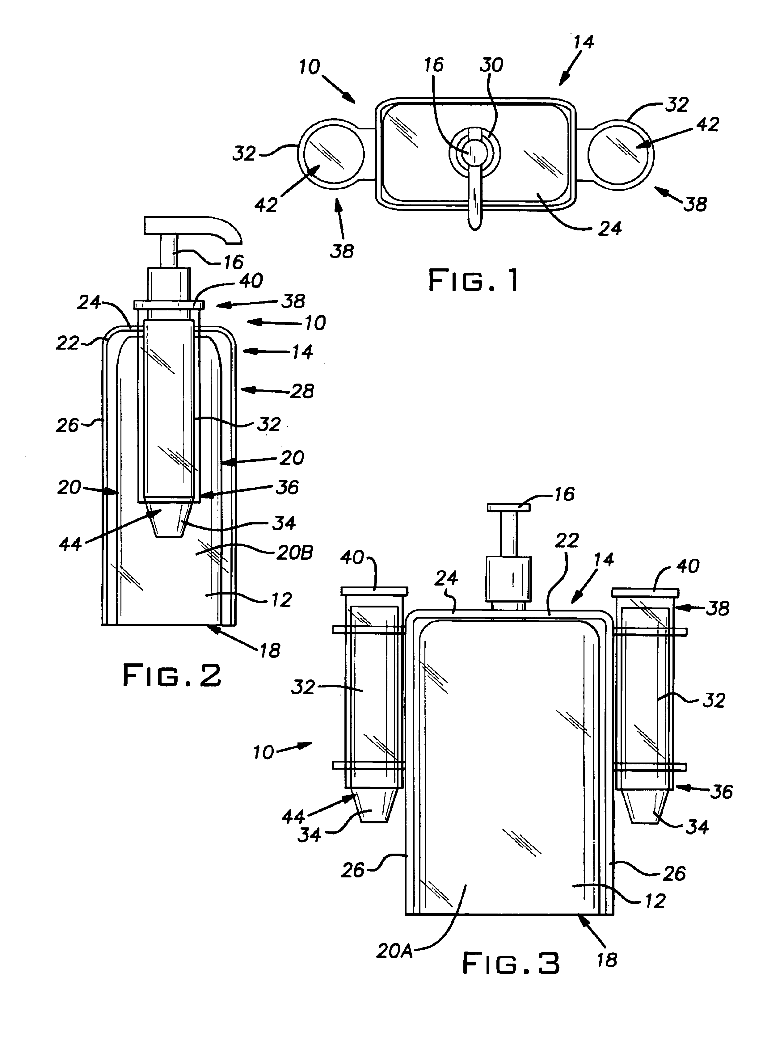
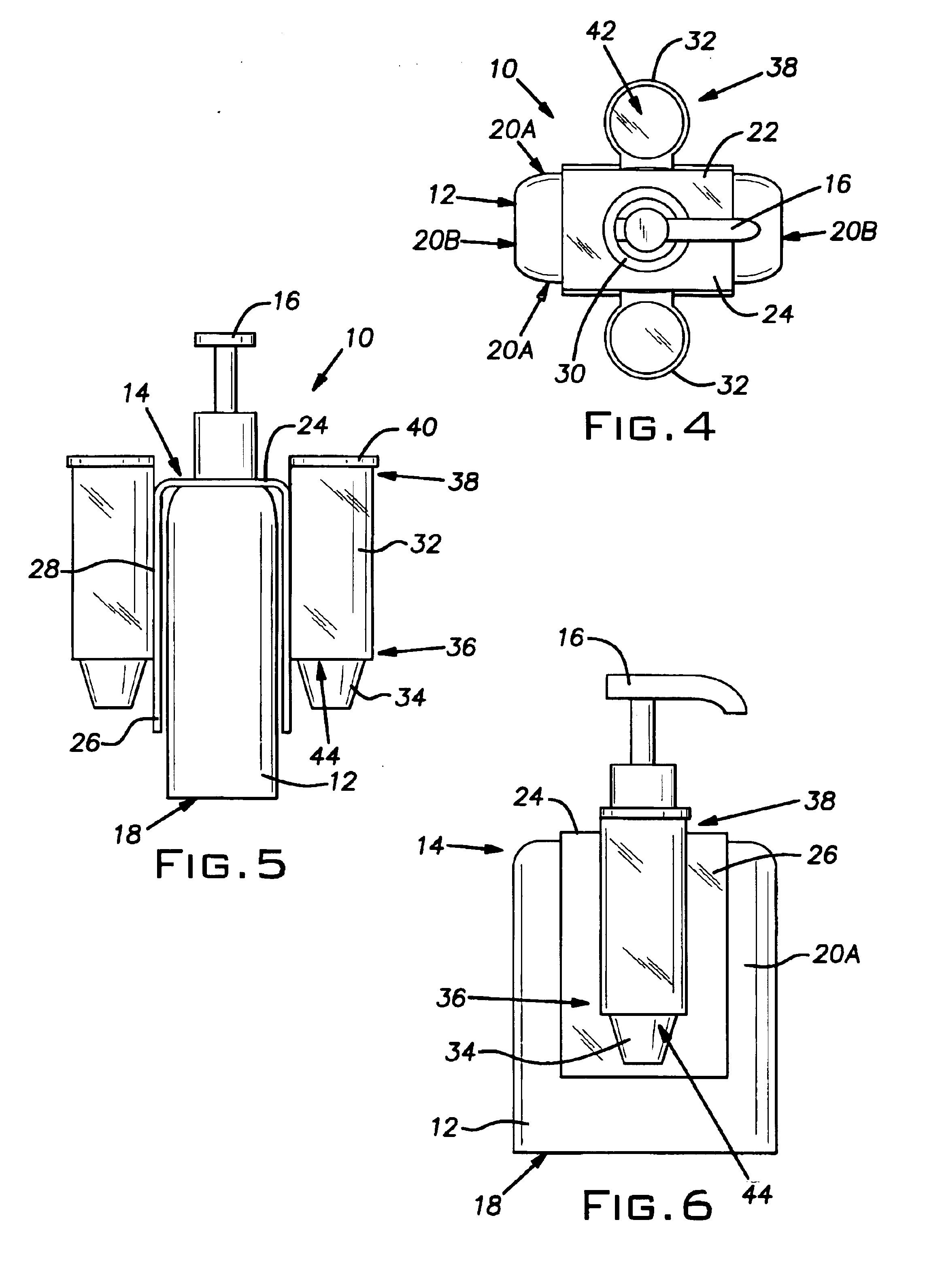
FIGS. 1-3 illustrate a first preferred embodiment of a cup dispenser 10 according to the present invention. The cup dispenser 10 is designed for use with a bottle 12 having a top 14 with a liquid dispenser 16 mounted thereon, and a base 18 connected to the top 14 by one or more sides 20.

The cup dispenser 10 comprises a saddle 22 and a holder 32. The saddle 22 comprises a top panel 24 and one or more side panels 26 connected to and extending downwardly from the top panel 24. The embodiment illustrated in FIGS. 1-3 shows two side panels 26 located on opposing sides of the top panel 24. The top panel 24 and side panels 26 cooperate to form a housing 28 that covers the top 14 of the bottle 12 and two sides 20 of the bottle 12, the top panel 24 having an opening 30 sized to accommodate the liquid dispenser 16 of the bottle 12. When the liquid dispenser 16 is inserted through the opening 30, the saddle 22 engages the bottle 12. An example of a preferred liquid dispenser is a pump, as the ...


PUM


Abstract

The present invention provides a cup dispenser for holding cups adjacent to the dispenser. The cup dispenser is designed for use with a bottle having a liquid dispenser mounted thereon, and includes a saddle and a holder. The saddle includes a top panel including an opening sized to accommodate the liquid dispenser of the bottle, and one or more side panels connected to and extending downwardly from the top panel. When the liquid dispenser is inserted through the opening, the saddle engages the bottle. The holder extends from a side panel and is configured to receive a plurality of vertically stacked cups. There are many advantages associated with the cup dispenser of the present invention. Dispensing liquids such as mouthwashes, fluoride solutions, medications, and refreshments becomes more convenient and more sanitary using the cup dispenser of the present invention.

Description

BACKGROUND OF THE INVENTION1. Field of InventionThe present invention relates to a cup dispenser, and more particularly to a cup dispenser configured to attach to a bottle having a liquid dispenser mounted thereon.2. Description of Related ArtLiquids such as mouthwashes, fluoride solutions, medications, and refreshments are often dispensed into disposable cups. For example, in the facilities of professional oral care providers, there is a need to supply cups for mouth rinsing. Often, the cups are placed on a table or countertop next to a liquid dispenser. However, tables and countertops are not the most sanitary locations for stacks of disposable cups. Cup users must handle the entire stack of cups to remove a cup from the stack. Additionally, the cups contact the surfaces and are exposed to microorganisms and debris that remain on the surfaces even though the surfaces appear clean to the naked eye. Other cup users and unsanitary surfaces foster the spread of diseases.A convenient l...

Claims


Application Information

Patent Timeline
Patent Type & Authority Patents(United States)
IPC IPC(8): A47F1/08A47F1/00
CPCA47F1/085
Inventor MEHES, PAUL L.BLOOM, DANIEL H.
Owner MEHES PAUL L
Why Eureka
Try Eureka