Systems and methods of inventory management utilizing unattended facilities

a technology of inventory management and secure facilities, applied in the direction of burglar alarm mechanical actuation, burglar alarm by hand-portable article removal, instruments, etc., can solve the problems of service failure, inconvenient and time-consuming, incurring additional courier costs and delay time, etc., to accelerate the processing of the return part, cost saving, cost saving

Inactive Publication Date: 2005-03-15
UNITED PARCEL SERVICE OF AMERICAN INC
View PDF53 Cites 123 Cited by
  • Summary
  • Abstract
  • Description
  • Claims
  • Application Information

AI Technical Summary

Benefits of technology

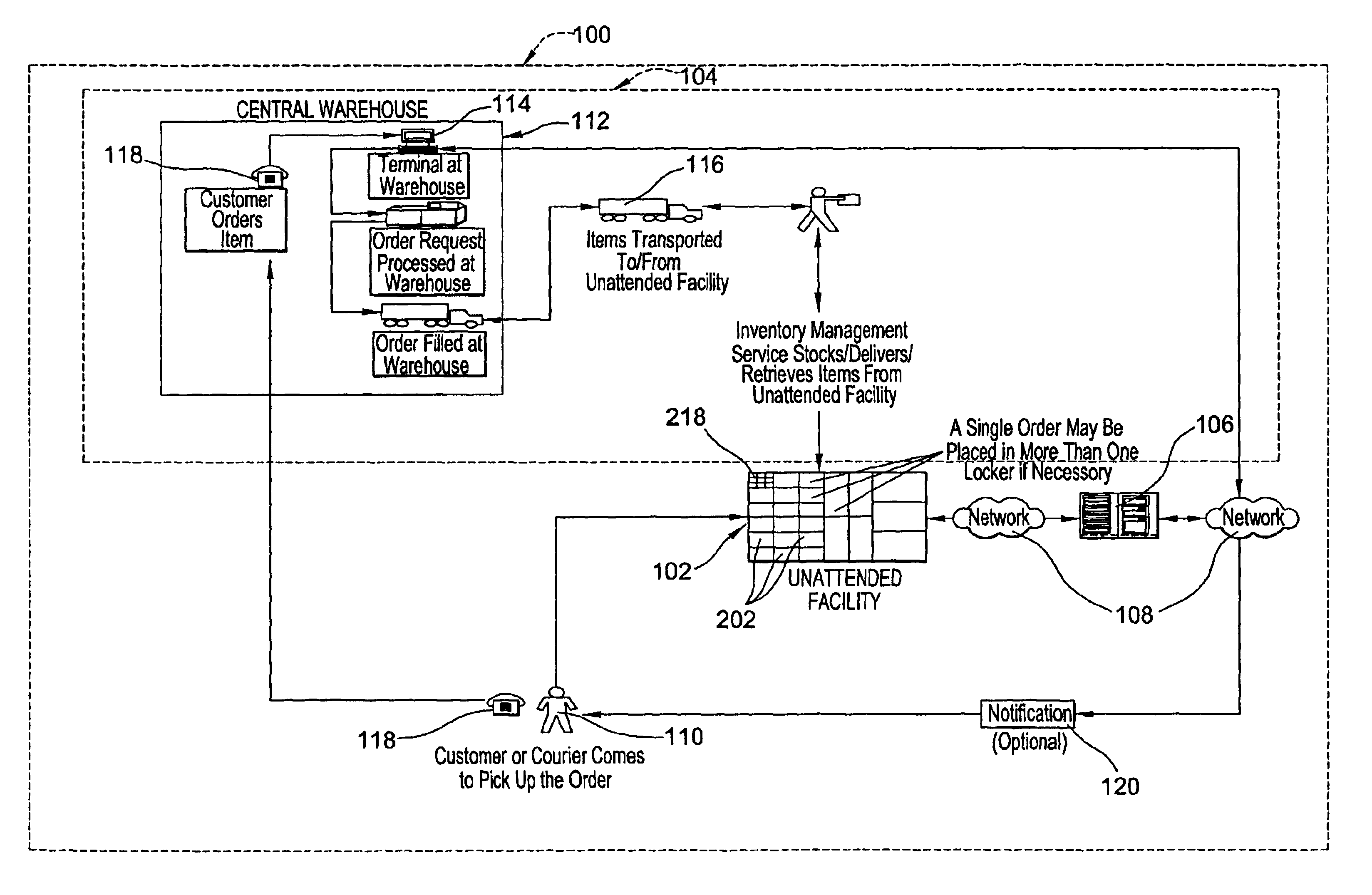
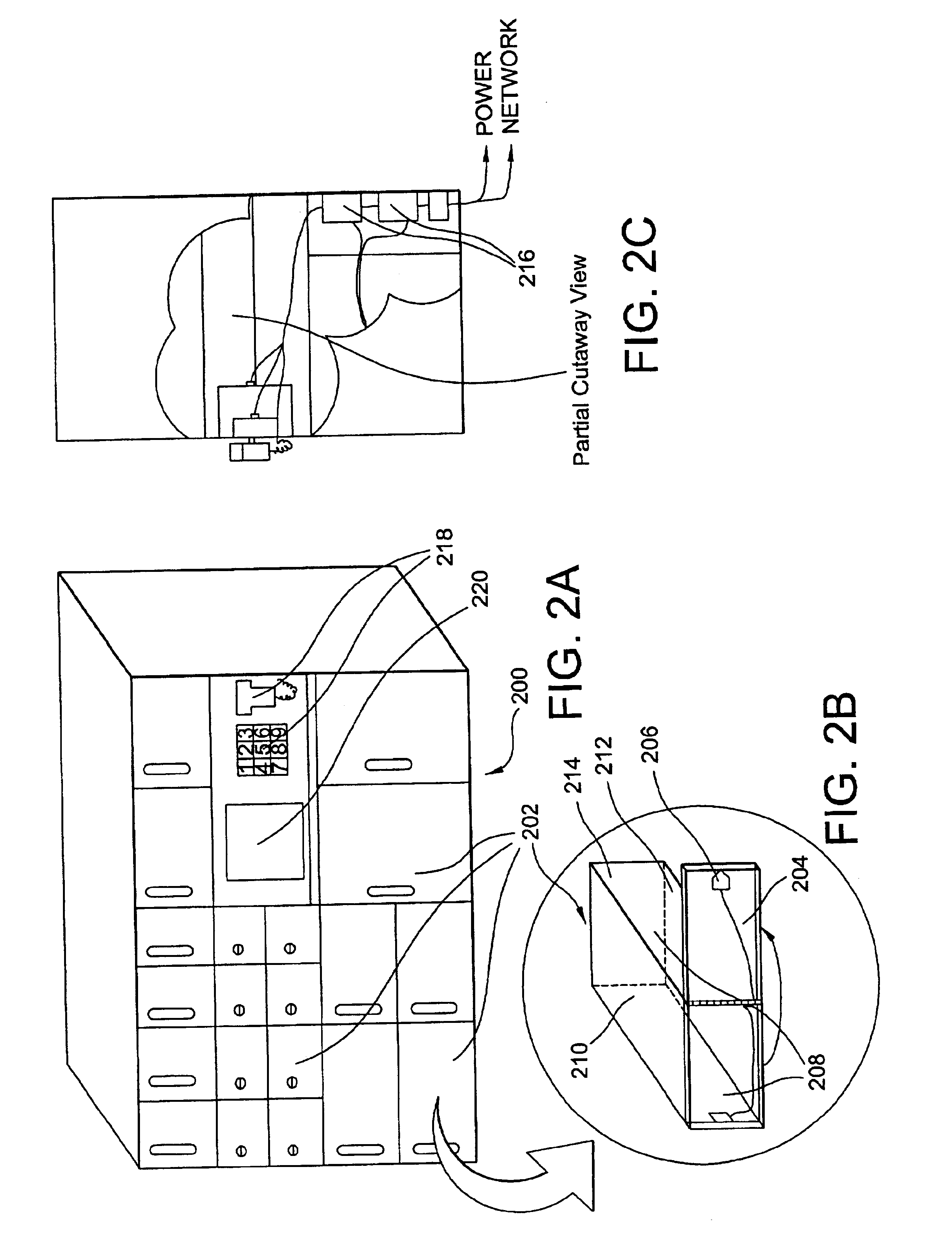
The return part is then deposited into a secure locker, bin or other enclosure that is associated with the unattended drop off facility. Information entered by the user into the data entry device at the unattended drop off facility location is transferred by one or more processors associated with the unattended drop off facility via a network to a central server. Such information avoids the user from having to await a return authorization from the inventory management service or a manufacturer. The entered information is also transmitted to the inventory management service long before the return part is moved and allows pre-processing of the return part to begin which accelerates the processing of the return part. Inventory management decisions may also be made from the return parts information. In one embodiment, the remote unattended drop off facility may be associated with a remote unattended inventory facility. For instance, the unattended drop off facility may be co-located with an unattended inventory facility or the unattended drop off facility may be incorporated into the unattended inventory facility. In this embodiment, for example, the central server will check the inventory quantities at the unattended inventory facility of the particular part that is being returned. If the inventory quantities are below a designated level and the return part is identified as “good,” the return part may be placed in the inventory of the associated unattended inventory facility. This may be accomplished by the technician placing the “good” part in a certain bin and quantity of the inventory of that part at that unattended inventory facility incremented. Or, inventory management personnel may transfer the “good” part from a bin associated with the unattended drop off facility to a locker associated with the unattended inventory facility and increment the inventory quantity of the unattended inventory facility. If the inventory quantities at the remote unattended inventory facility are in excess of a designated maximum, inventory management personnel or a courier may return the part to a centralized warehouse or any other attended facility, or the part may be placed in the inventory of another unattended inventory facility. The present invention is capable of monitoring the inventory quantities of attended and unattended facilities and distribute “good” return items to facilities where they are most needed. Furthermore, this may result in cost savings over the traditional method of transporting all return parts to a central warehouse and then distributing them to where they are needed.
The present invention makes parts that are required for service more readily available. Further, cost savings may be realized through inventory consolidation, courier run consolidation, reduced labor costs, increased technician efficiency, and faster return processing. The system is more flexible than traditional warehouse inventory management as the remote unattended inventory facilities and unattended drop off facilities may be strategically located near customers without the expense of a traditional warehouse. Advantageously, inventory items may be pooled among a plurality of customers. For example, an unattended inventory facility may be strategically located near two customers. Each of these two customers may have an occasional, infrequent need for a high-cost part. Inventory costs may be reduced by the two customers (or one service provider that serves both customers) reaching an agreement to keep one of the high-cost, low-demand parts in the secure unattended facility rather than each customer keeping a separate one of the high-cost parts on-hand. Also, the remote unattended facilities may be re-located if necessary with relatively small expense.

Problems solved by technology

First, this method requires technicians to travel to a warehouse each time they need a new part, which can be inconvenient and time consuming.
This can incur added courier costs and delay time while the technician waits to meet the courier.
Moreover, if the courier and the technician fail to meet, it may cause a service failure.
Second, the parts distribution method described above only allows technicians to pick up parts when the attended warehouse is staffed and open for business or requires extra expense or extraordinary arrangements for “after-hours” pickup.
Third, because the warehouses are often busy, technicians often have to wait in line before receiving their requested parts from a warehouse representative, thus further delaying the repair.
Although such locker systems reduced some problems with early warehouse part distribution systems (such as waiting in line and only being able to access the parts when the distribution center is staffed), there are still many problems associated with these systems.
Furthermore, such systems do not provide for a convenient method of allowing users to return damaged or unused parts or, if such parts are returned, the returning technician may need to obtain some form of authorization prior to dropping off the returned part at the unattended facility.
These multiple notifications for a single order are often inconvenient and confusing for the technician ordering the part as well as increasing the messaging traffic.

Method used


Image

  • Systems and methods of inventory management utilizing unattended facilities
  • Systems and methods of inventory management utilizing unattended facilities
  • Systems and methods of inventory management utilizing unattended facilities

Examples


Embodiment Construction

The present inventions now will be described more fully hereinafter with reference to the accompanying drawings, in which some, but not all embodiments of the invention are shown. Indeed, these inventions may be embodied in many different forms and should not be construed as limited to the embodiments set forth herein; rather, these embodiments are provided so that this disclosure will satisfy applicable legal requirements. Like numbers refer to like elements throughout.

The present invention is described below with reference to block diagrams and flowchart illustrations of methods, apparatuses (i.e., systems) and computer program products according to an embodiment of the invention. It will be understood that each block of the block diagrams and flowchart illustrations, and combinations of blocks in the block diagrams and flowchart illustrations, respectively, can be implemented by computer program instructions. These computer program instructions may be loaded onto a general purpos...


PUM


Abstract

An inventory management system utilizes unattended facilities remote from a central warehouse for service parts logistics. Items are placed in inventory in secure enclosures at the unattended facilities by the inventory management service. The unattended facilities may be located near one or more customers to reduce a service technician's travel time and customers' inventory costs. A service technician utilizes a passcode to retrieve needed items. The service technician may order items that are not kept in the inventory of the unattended facility in which case the items may be delivered to the unattended facility and the service technician may receive a notification related to all the items that comprise an order that the order is ready for pick up at an unattended facility. Unused, used or damaged parts may be returned by a technician to a remote secure enclosure where such returned parts may be retrieved and disposed of, repaired or placed back into inventory if not damaged or after repair, and the processing of such returned parts begins by information entered into a data entry device at the remote secure enclosure location. Return items that are not damaged may be included in the inventory of an unattended facility.

Description

BACKGROUND OF THE INVENTION1. Field of the InventionThe present invention relates generally to inventory management utilizing unattended secure facilities and more particularly to systems and methods for the distribution of service parts from a supplier to a user and for the return of parts from the user to a supplier or other entities utilizing unattended facilities.2. Description of Related ArtTechnicians (such as computer repair technicians) often require new parts in order to complete a particular repair. Generally, in the past, when a technician needed a new part, the worker would request the part from a warehouse, travel to the warehouse, pick up the part at an attended distribution counter within the warehouse, travel to the place where the part was needed, and then install the part.The parts distribution method described above has several drawbacks. First, this method requires technicians to travel to a warehouse each time they need a new part, which can be inconvenient and ...

Claims


Application Information

Patent Timeline
Patent Type & Authority Patents(United States)
IPC IPC(8): G06Q10/00G06Q30/00G06Q10/08G06Q30/06
CPCG06Q10/087G07F17/12G06Q30/06G07F17/13
Inventor KNOWLES, CLYDE W.FRATT, DOUGLAS DAVIDJOYCE, ROBERT F.BONG, JUWONO W.
Owner UNITED PARCEL SERVICE OF AMERICAN INC
Why Eureka
Try Eureka