Temporary intraluminal filter guidewire and methods of use

a filter guidewire and guidewire technology, applied in the field of intraluminal devices, can solve the problems of limiting the ability of the guidewire to negotiate tortuous vascular anatomy, infarction or stroke, guidewire-based filter devices do not have the handling characteristics expected of steerable guidewires, etc., to achieve the effect of enhancing radiopacity and minimizing the effect of physical properties of the wires

Inactive Publication Date: 2005-03-15
MEDTRONIC AVE
View PDF52 Cites 225 Cited by
  • Summary
  • Abstract
  • Description
  • Claims
  • Application Information

AI Technical Summary

Benefits of technology

In one embodiment of the invention, the guidewire includes a moveable core wire having a tapered distal end to which the distal end of the filter is attached. The proximal end of the filter is attached to the distal end of the guidewire tubular shaft. The guidewire shaft includes a stiff, elongate proximal portion for steering and transmitting axial force, and a relatively flexible distal portion for negotiating tortuous vascular anatomy. A transition sleeve is fixed to the core wire and fits slidingly inside the distal end of the tubular shaft. The sleeve extends distal to the shaft, providing a smooth transition in stiffness where an abrupt change would otherwise occur. The combination of tapered core wire, flexible distal shaft region and transition sleeve results in a filter guidewire with handling characteristics that are comparable to standard steerable guidewires.
Another embodiment of the invention is built around a standard-type steerable guidewire, which includes an elongate shaft having a distal region surrounded by a flexible tubular element, such as a coiled spring. Both the proximal and distal ends of a self-expanding tubular filter assembly are slidably mounted adjacent the distal end of the guidewire, with a stop element fixed to the guidewire between the filter ends to limit axial movement thereof. Mounted to the proximal end of the filter is a sliding actuator, which is selectively engageable with a hollow rod slidably disposed over the guidewire. Proximally directed force can be applied to the filter proximal end by pulling the combination of the rod and the actuator while pushing the guidewire distally. A first degree of such proximally directed force will collapse the filter by separating the filter proximal end from the filter distal end, which is restrained against proximal movement by the stop element. A second, higher degree of proximally directed force will disengage the rod from the actuator, permitting the rod to be withdrawn from the patient and allowing the filter to self-expand.
To provide a temporary filter with enhanced radiopacity, but with undiminished physical performance, radiopaque material is added to one or more braiding wires, in the centers thereof, where the effect on physical properties of the wires is minimized.

Problems solved by technology

During each of these procedures, there is a risk that emboli dislodged by the procedure will migrate through the circulatory system and cause infarction or strokes.
However, the guidewire-based filter devices do not have the handling characteristics expected of steerable guidewires.
Abrupt transitions in stiffness in the area of the filter can limit the ability of the guidewire to negotiate tortuous vascular anatomy.
Such device limitations can restrict the number of patients receiving the benefits of filtration during interventional vascular procedures.
Filter guidewires that use a moveable core wire to actuate the filter also have diminished performance characteristics.
Another problem associated with prior art filter guidewires is the requirement for a sheath to envelop and collapse the filter before and after the treatment is performed.
Sheaths that encase the filter often require large bores, with attendant bulky handling.
It is time-consuming and cumbersome to exchange the sheath for the treatment catheter and to reverse this exchange step at the end of the procedure.
Another problem associated with self-expanding temporary filters is visualization of the filter under fluoroscopy.
Filter braiding materials having good mechanical properties are not also very radiopaque to X-rays typically used during clinical procedures.
Solutions to this problem typically require the addition of radiopaque material to the braiding wires, which often diminishes their shape-memory or elastic properties, or both.

Method used


Image

  • Temporary intraluminal filter guidewire and methods of use
  • Temporary intraluminal filter guidewire and methods of use
  • Temporary intraluminal filter guidewire and methods of use

Examples


first embodiment

Referring now to FIG. 5, in the invention, filter guidewire 20 includes core wire 42 and flexible tubular tip member 43, which is preferably a coil spring, fixed around the distal end of core wire 42. Thin wires made from stainless steel and / or one of various alloys of platinum are commonly used to make such coil springs for use in guidewires. Core wire 42 can be made from shape memory metal, such as nitinol, or preferably is a stainless steel wire tapered at the distal end. For treating small caliber vessels such as coronary arteries, core wire 42 will preferably measure about 0.006 inch (0.15 mm) in diameter.

Tubular shaft 44 is slidably disposed around core wire 42, and includes relatively stiff proximal portion 46 and relatively flexible distal portion 48. Proximal portion 46 is preferably made from thin walled stainless steel tubing, usually referred to as hypotubing, although other metals can be used. Various metals or polymers can be used to make relatively flexible distal por...

second embodiment

FIG. 6 depicts the invention in which filter guidewire 51 incorporates a typical steerable guidewire 55 and deploys a self-expanding filter. Guidewire 55 comprises core wire 52, including a tapered distal end, and flexible tubular tip member 54, which is preferably a coiled spring, fixed there around. At least a distal portion of tip member 54 is preferably made from radiopaque metal wire, such as an alloy of platinum. Self-expanding filter 25 is mounted about guidewire 55, with filter distal and proximal ends 27, 29 being mounted slidably there along and, optionally, being fitted with radiopaque markers (not shown). Filter proximal end 29 is attached to actuator 63 using adhesive or solder. Actuator 63 is mounted slidably about guidewire 55 and is preferably made of shape memory metal, such as nitinol. Actuator 63 is illustrated in FIG. 7, with alternative actuators 163, 263 and 363 depicted in FIGS. 8, 9 and 10, respectively. In actuator 163, a series of ridges having increasing d...

third embodiment

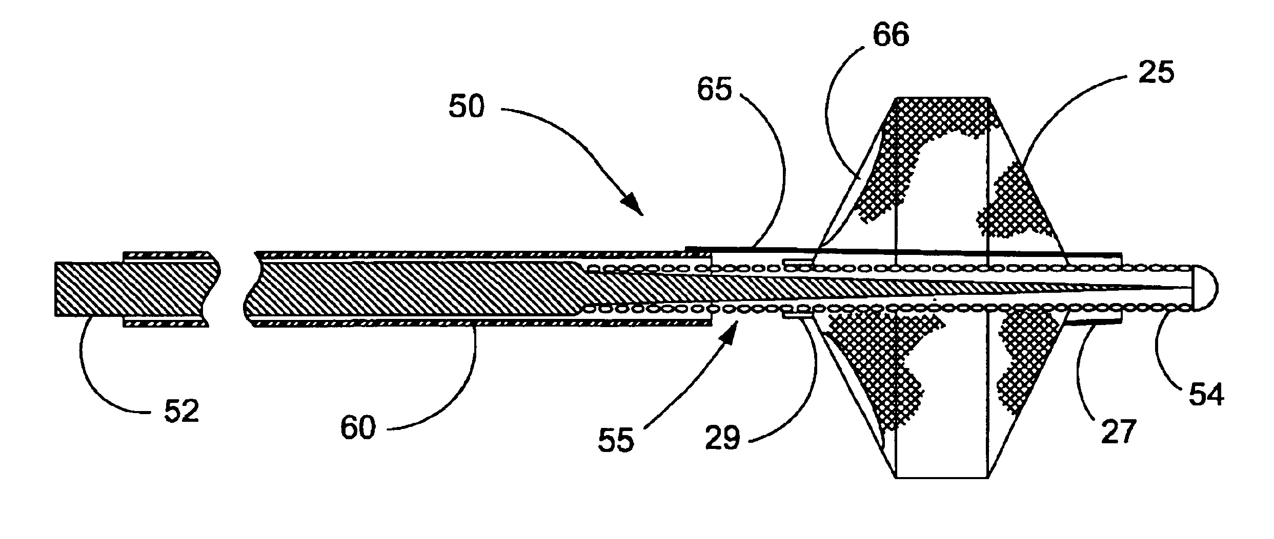
FIG. 11 illustrates the invention in which filter guidewire 50 also incorporates steerable guidewire 55, as described above with respect to filter guidewire 51. In filter guidewire 50, the mounting arrangement of filter 25 is reversed with respect to filter guidewire 20, such that filter distal end 27 is slidably mounted around and adjacent to the distal end of guidewire 55, and filter proximal end 29 is fixed to guidewire 55. Elongate tubular actuator 60 is slidingly and coaxially disposed around guidewire 55 proximal to filter 25. Link 65 movably extends through opening 66 in filter 25 adjacent filter proximal end 29 and connects the distal end of actuator 60 to filter distal end 27. Opening 66 is one of the inlet openings of filter 25, however any opening large enough to slidably pass link 65 will suffice. For example, a standard or over-sized pore in filter 25 may permit link 65 to extend therethrough. Actuator 60 can be made from thin walled metal tubing, such as stainless stee...


PUM


Abstract

The present invention is a temporary intraluminal filter guidewire for use during interventional procedures, such as angioplasty or stent deployment. A braided filter is mounted near the distal end of a steerable guidewire, which guides a therapeutic catheter. An actuator rod slides over the guidewire and is removably connected to the filter. The rod controls relative displacement of the filter ends, causing transformation of the filter between a deployed configuration and a collapsed configuration. Wire having enhanced radiopacity is included in the filter to provide visualization under fluoroscopy.

Description

FIELD OF THE INVENTIONThe present invention relates generally to intraluminal devices for capturing particulate in the vessels of a patient. More particularly, the invention relates to a filter for capturing emboli in a blood vessel during an interventional vascular procedure and then removing the captured emboli from the patient after completion of the procedure. Furthermore, the invention concerns a filter mounted on a guidewire that can also be used to direct an interventional catheter to a treatment site within a patient.BACKGROUND OF THE INVENTIONA variety of treatments exists for dilating or removing atherosclerotic plaque in blood vessels. The use of an angioplasty balloon catheter is common in the art as a minimally invasive treatment to enlarge a stenotic or diseased blood vessel. When applied to the vessels of the heart, this treatment is known as percutaneous transluminal coronary angioplasty, or PTCA. To provide radial support to the treated vessel in order to prolong th...

Claims


Application Information

Patent Timeline
Patent Type & Authority Patents(United States)
IPC IPC(8): A61F2/01A61B17/00A61B17/22A61M25/00
CPCA61F2/013A61F2002/015A61F2230/0069A61F2230/0071A61F2230/0006A61B2017/1205A61B2017/12095A61F2002/018A61F2230/008
Inventor DOUK, NAREAKRAFIEE, NASSERBRIN, DAVID S.STRICKLER, PETER G.
Owner MEDTRONIC AVE
Why Eureka
Try Eureka