Ozone treatment method and ozone treatment apparatus

a technology of ozone treatment and ozone treatment, which is applied in the direction of cleaning processes and equipment, photomechanical treatment, instruments, etc., can solve the problems of unreachable treatment or no treatment of the cooled surface, and the need to perform the treatment for an extended period of time, and achieve the effect of short tim

Inactive Publication Date: 2005-03-15
SUMITOMO PRECISION PROD CO LTD
View PDF7 Cites 3 Cited by
  • Summary
  • Abstract
  • Description
  • Claims
  • Application Information

AI Technical Summary

Benefits of technology

By so doing, in the early stage where the spacing between the substrate and the opposed plate is relatively large, the portion directly below the discharge port and its neighboring portions on the substrate surface can be reliably treated, though the area that can be treated is small, and thereafter, by gradually closing the spacing between the substrate and the opposed plate and thereby increasing the flow velocity of the gas stream, the treatment area is gradually increased, as a result of which the large surface area of the substrate can be treated. In this way, by gradually closing the spacing between the substrate and the opposed plate, the large surface of the substrate can be treated uniformly and in a short time.
Further, the substrate and the opposed plate may be moved closer to / away from each other in a periodic or non-periodic manner so as to vary the spacing between them in a periodic or non-periodic manner; in this case, the closing speed may be decreased progressively or in a steplike manner. In this case also, the same effect as described above can be achieved.

Problems solved by technology

This has resulted in uneven treatment or no treatment of the cooled surface portions of the wafer W. If the occurrence of such unevenly treated or untreated portions is to be prevented, it has been necessary to perform the treatment for an extended period of time.

Method used


Image

  • Ozone treatment method and ozone treatment apparatus
  • Ozone treatment method and ozone treatment apparatus
  • Ozone treatment method and ozone treatment apparatus

Examples


Embodiment Construction

The present invention will be described in further detail below with reference to the accompanying drawings.

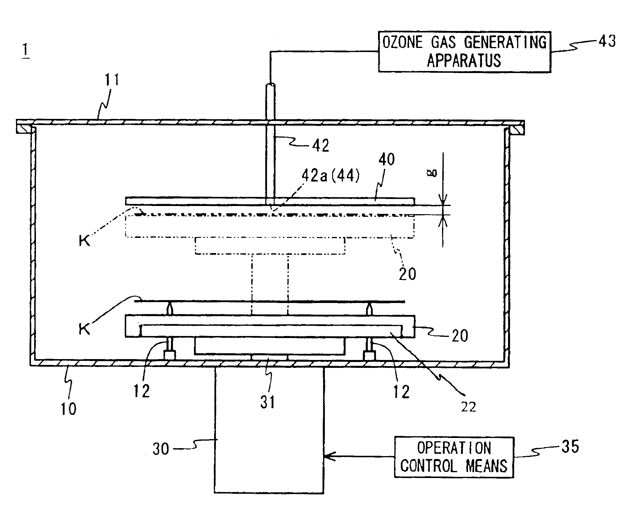
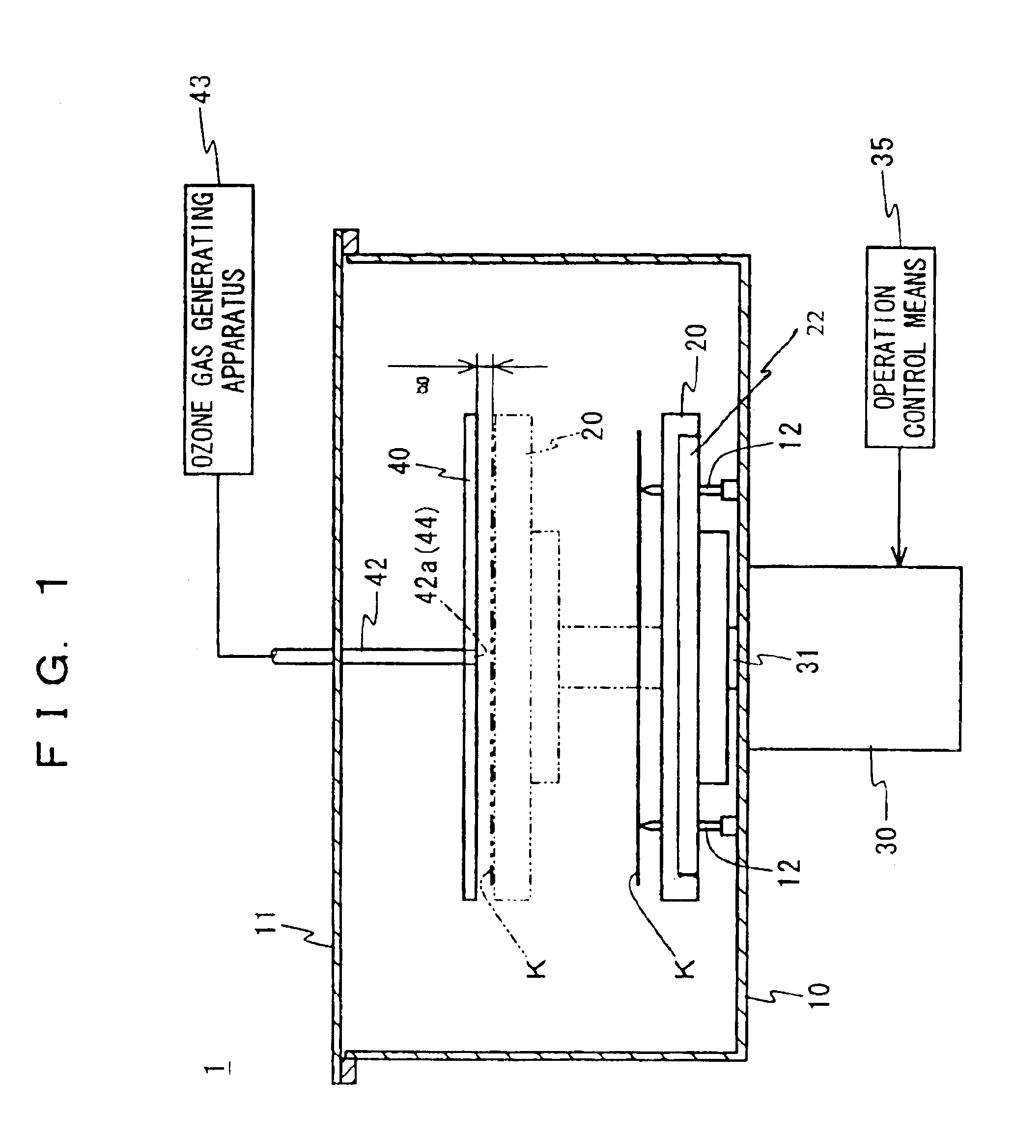
As shown in FIG. 1, the ozone treatment apparatus 1 according to the present invention comprises a treatment chamber 10 having a prescribed internal volume, a placement table 20 which disposed inside the treatment chamber 10 and which a substrate K is placed on the upper surface thereof, a lift means 30 for moving the placement table 20 up and down, a control means 35 for controlling the operation of the lift means 30, and an opposed plate 40 positioned above the placement table 20.

The treatment chamber 10 is constructed so that it is closed with a lid member 11, and so that gases inside the treatment chamber 10 are exhausted as needed to the exterior through an outlet port (not shown). The treatment chamber 10 has a load / unload opening (not shown) through which the substrate K is loaded into or unloaded from the treatment chamber 10.

Further, a plurality of supporting needles ...


PUM


Abstract

The invention concerns an ozone treatment method and an ozone treatment apparatus for performing a treatment such as the formation and reformation of an oxide film, the removal of a resist film by blowing an ozone gas onto a surface of a substrate such as a semiconductor substrate or liquid crystal substrate. The ozone treatment apparatus 1 includes: a placement table 20 on which the substrate K is placed; a heating unit for heating the substrate K placed on the placement table 20; an opposed plate 40, disposed opposite the substrate K, for discharging the ozone gas through a discharge port 44 formed in a surface facing the substrate K, a gas feeding means 43 for feeding the ozone gas into the discharge port 44; a lifter 30 for moving the placement table 20 up and down; and a control unit 35 for controlling the operation of said lifter 30. During the discharge of the ozone gas, the control unit 35 operates the lifter 30 so as to vary the spacing g between the opposed plate 40 and the substrate K placed on the placement table 20.

Description

TECHNICAL FIELDThe present invention relates to an ozone treatment method and an ozone treatment apparatus wherein a treatment gas containing at least ozone is blown onto a surface of a substrate such as a semiconductor substrate or liquid crystal substrate for the purpose of forming an oxide film on the substrate surface or of reforming the oxide film formed on the substrate surface or removing the resist film formed on the substrate surface.BACKGROUND ARTPrior known examples of the above ozone treatment apparatus include the ashing apparatus disclosed in Japanese Unexamined Patent Publication No. 5-166718. As shown in FIG. 3, the ashing apparatus 100 comprises a placement table 101 on the upper surface of which a wafer W is placed, a transparent quartz plate 102 disposed above the wafer W by being spaced a prescribed distance g away from the surface of the wafer W, a nozzle 103 disposed with its one end opening in the surface of the quartz plate 102 that faces the wafer W, and a p...

Claims


Application Information

Patent Timeline
Patent Type & Authority Patents(United States)
IPC IPC(8): H01L21/00H01L21/306
CPCH01L21/67253H01L21/67017H01L21/306
Inventor KIKUCHI, TATSUOYAMANAKA, TAKEOYAMAGUCHI, YUKITAKAKANAYAMA, TOKIKO
Owner SUMITOMO PRECISION PROD CO LTD
Why Eureka
Try Eureka