
Infrared element and oven

a technology of infrared element and oven, which is applied in baking ovens, ovens, lighting and heating apparatus, etc., can solve the problems of increasing the complexity of dual-lane ovens, increasing the difficulty of oven operation, repair and maintenance, and inaccessible interior connections, so as to improve construction and operation.

Active Publication Date: 2005-03-15
MARLEN INT
View PDF8 Cites 26 Cited by
  • Summary
  • Abstract
  • Description
  • Claims
  • Application Information

AI Technical Summary

Benefits of technology

The present invention provides an improved infrared element and an improved dual lane continuous oven which satisfy the needs and alleviate the problems discussed above. The invention allows the element connections within the interior of the oven between the dual lanes to be eliminated and allows all of the elements in each lane to be installed and connected through an outer wall of the oven. Moreover, the present invention allows each individual conveyor lane to retain its own individual series of upper infrared elements arching from the outer lateral side to the inner lateral side of the conveyor. The direct irradiation of the products on each conveyor is therefore very consistent and uniform and cannot be blocked or shadowed by products traveling down the other conveyor. In addition, the present invention can improve the construction and operation of even a single lane oven by allowing all of the element connections to be made and accessed through one side of the housing.

Problems solved by technology

Such interior connections are not readily accessible and (a) significantly increase the complexity of the dual lane oven versus a single lane oven, (b) can require the use of materials capable of withstanding higher temperatures within the central part of the oven, (c) typically require that both processing lanes be shut down when a problem in one lane occurs, and (d) can make the oven more difficult to operate, repair, and maintain.
Previous attempts to address these shortcomings have not been successful.
Unfortunately, the use of such elements results in (a) the inner sides of the products on each belt being shadowed by the products traveling down the other belt and / or (b) the upper infrared elements being much closer to the outer side of the product than to the innerside.
Thus, the use of elements of this type would result in uneven, nonuniform irradiation and in inadequate heat transfer to the inner side of the product.

Method used


Image

  • Infrared element and oven
  • Infrared element and oven
  • Infrared element and oven

Examples


an embodiment 2

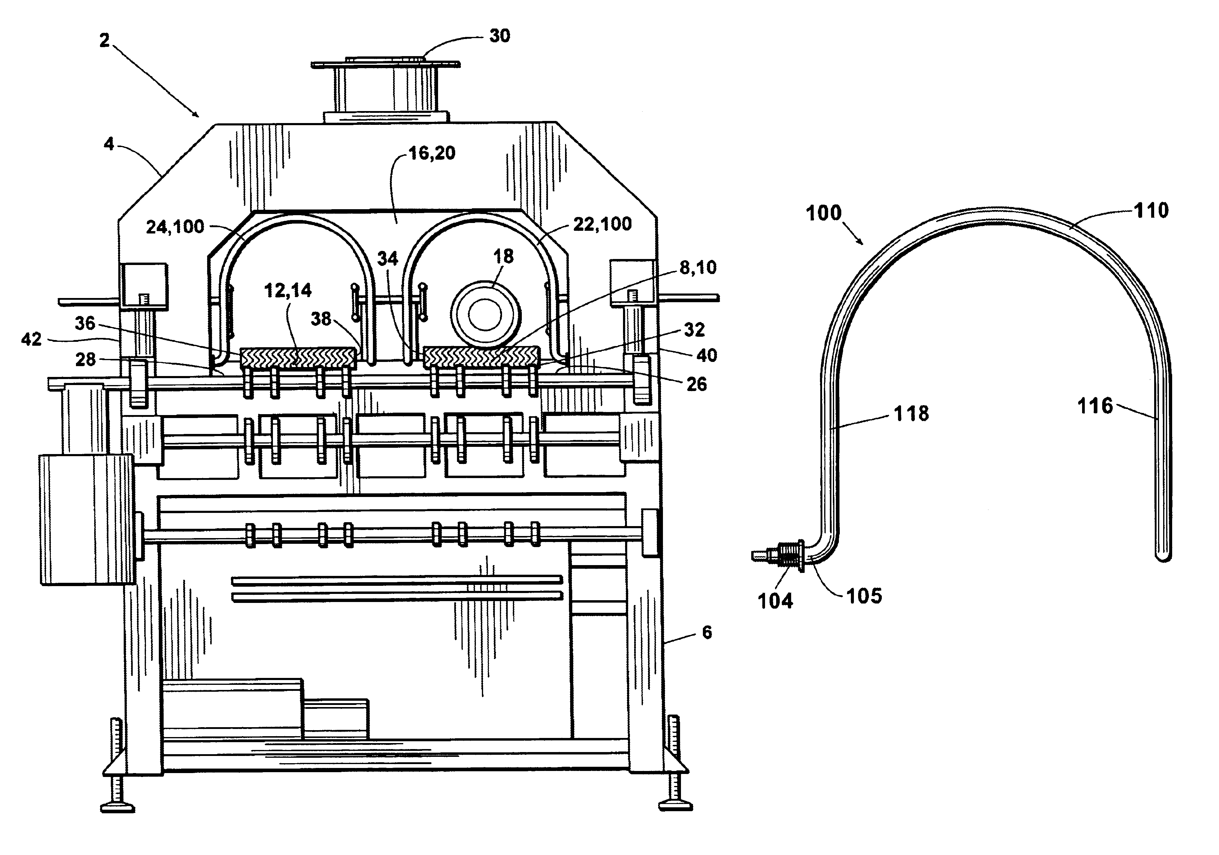
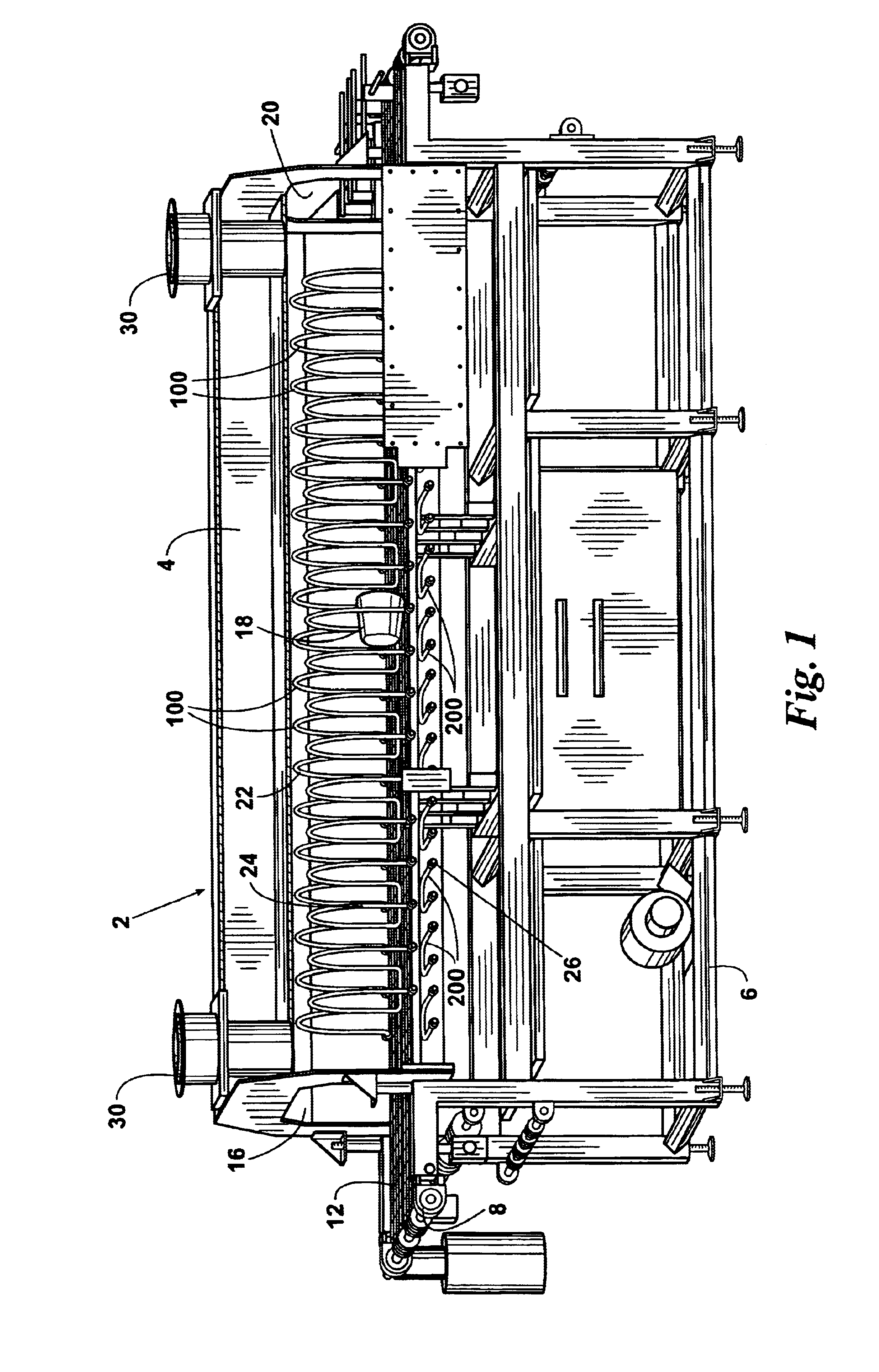
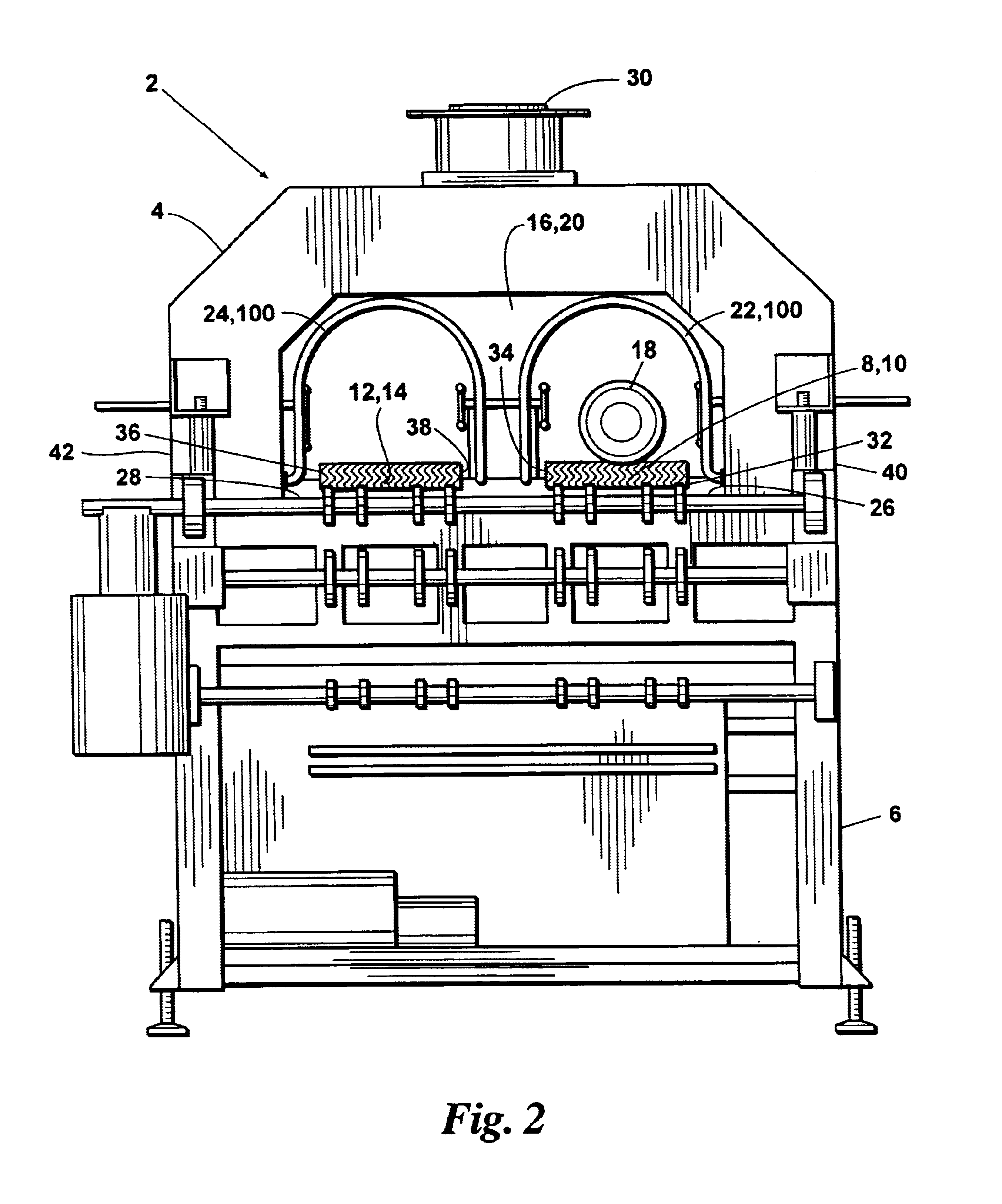
An embodiment 2 of an improved dual lane infrared oven provided by the present invention is shown in FIGS. 1-3. The inventive dual lane oven 2 comprises: an elongate insulated housing 4 supported on a frame 6; a first conveyor 8 having a horizontal upper carrying run 10 which extends longitudinally through housing 4; a second conveyor 12 having a horizontal upper carrying run 14 which extends longitudinally through housing 4; a wide, inverted-U-shaped, inlet end opening in housing 4 for delivering products 18 to both of conveyors 8 and 12; a wide, inverted-U-shaped, outlet end opening 20 in housing 4 through which products 18 from both of conveyors 8 and 12 are delivered; a series 22 of lateral inventive upper infrared elements 100 positioned over the carrying run 10 of conveyor 8; a series 24 of lateral inventive upper infrared elements 100 positioned above the upper carrying run 14 of conveyor 12; a series 26 of lateral inventive lower infrared elements 200 positioned below the fi...

embodiment 100

The embodiment 100 of the inventive upper infrared element used in oven 2 is shown in FIGS. 4-7. The inventive upper infrared element 100 can be an electrical or gas infrared element and will preferably be electrical. The inventive upper element 100 comprises: a source terminal 102 and a return terminal 104 which are preferably adjacent to each other and are co-directional or otherwise directed so that, when installed in oven 2 over either of the conveyor carrying runs 10 or 14, both the source terminal 102 and the return terminal 104 will be located on the outer lateral side 32 or 36 of the carrying run 10 or 14 and will both be accessible through the same side wall 40 or 42 of the oven housing.

The inventive upper infrared element 100 further comprises: a distal turn-around portion 106 which will be positioned on the inner lateral side 34 or 38 of the conveyor carrying run; an outgoing element segment 108 having the source terminal 102 on an initial end portion 103 thereof and exte...

embodiment 200

Embodiment 200 of the lower infrared element provided by the present invention is shown in FIGS. 8 and 9. As with the inventive upper infrared element 100, the inventive lower infrared element 200 preferably includes a source terminal 202 and a return terminal 204 which are adjacent to each other and are co-directional or otherwise directed such that, when installed in inventive oven 2 beneath the conveyor carrying run 10 or 14, the source terminal 202 and the return terminal 204 will each be located on the outer lateral side 32 or 38 of the conveyor and will be accessible through the same side wall 40 or 42 of housing 4. To provide consistent uniform heating and irradiation across the bottom of the belt, the inventive lower infrared element 200 preferably comprises a straight outgoing segment 206 and a straight return segment 208 which will extend laterally beneath the conveyor carrying run in a spaced, parallel relationship.


PUM


Abstract

A continuous infrared oven and an infrared element therefor wherein the source and return terminals of the element are located on the same lateral side of the oven conveyor and are both accessible through the same oven side wall.

Description

FIELD OF THE INVENTIONThe present invention relates to improved infrared ovens and to improved infrared heating elements therefor.BACKGROUND OF THE INVENTIONOne example of an infrared oven heretofore used in the art is a continuous infrared oven available from Unitherm Food Systems, Inc. for removing purge material and free moisture from the surfaces of bag-cooked turkey breasts or hams prior to applying liquid smoke products or other browning liquids thereto. Another example of an infrared oven known in the art is a continuous infrared oven available from Unitherm Food Systems, Inc. for pasteurizing the surfaces of precooked food products prior to packaging.The continuous infrared ovens used in these applications typically comprise: an elongate insulated housing having inverted-U-shaped inlet and outlet openings; a conveyor (typically a stainless steel wire belt) having an upper carrying run extending longitudinally through the housing; and a series of inverted-U-shaped electrical ...

Claims


Application Information

Patent Timeline
IPC IPC(8): A21B2/00H05B3/00
CPCA21B2/00H05B3/0076H05B2203/032
Inventor HOWARD, DAVID
Owner MARLEN INT
Learn More