Constant current output control method and constant current output control device for switching power supply circuit

a technology of constant current output and control device, which is applied in the direction of electric variable regulation, process and machine control, instruments, etc., can solve the problems of increased cost, unstable and simple mass production of products having highly accurate constant current output characteristics, and excessive power not outpu

Inactive Publication Date: 2005-03-15
SMK CORP
View PDF6 Cites 52 Cited by
  • Summary
  • Abstract
  • Description
  • Claims
  • Application Information

AI Technical Summary

Benefits of technology

Thus, comparison is made with the set current Ipset to which δt×Vcc÷Lp is added, and the primary winding current Ip when the oscillating switching device is switched to OFF is set to be substantially equal to the set current Ipset. Accordingly, it is

Problems solved by technology

Conventionally, in this type of switching power supply circuit, an output voltage and current of a rectifying smoothing circuit of a secondary side are monitored such that excessively high power is not output from the rectifying smoothing circuit of the secondary side.
However, as a result of variation of circuit constants of the these circuit devices, variation of the integrated circuit itself when the switching control circuit 101 acts as an integrated circuit, and the like, a problem arises since s

Method used


Image

  • Constant current output control method and constant current output control device for switching power supply circuit
  • Constant current output control method and constant current output control device for switching power supply circuit
  • Constant current output control method and constant current output control device for switching power supply circuit

Examples


third embodiment

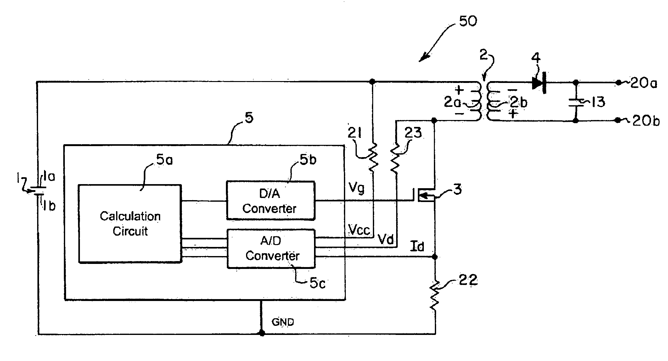
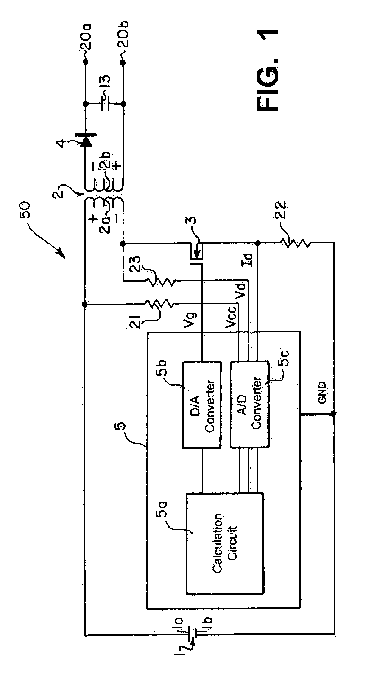
FIG. 4 is a circuit diagram of a switching power supply circuit 60 according to the present invention. Switching power supply circuit 60 is provided with an auxiliary winding 2c at the primary side of the transformer 2, and monitors a voltage V2c of the auxiliary winding 2c to detect an output time T2.

The switching power supply circuit 60, as compared to the switching power supply circuit 50 shown in FIG. 1, only differs with respect to the fact that the auxiliary winding 2c is additionally provided in the transformer 2, and the analog input terminal Vd of the A / D converter of the switching control circuit 6 is connected to a low voltage side end portion of the auxiliary winding 2c via the resistor 24.

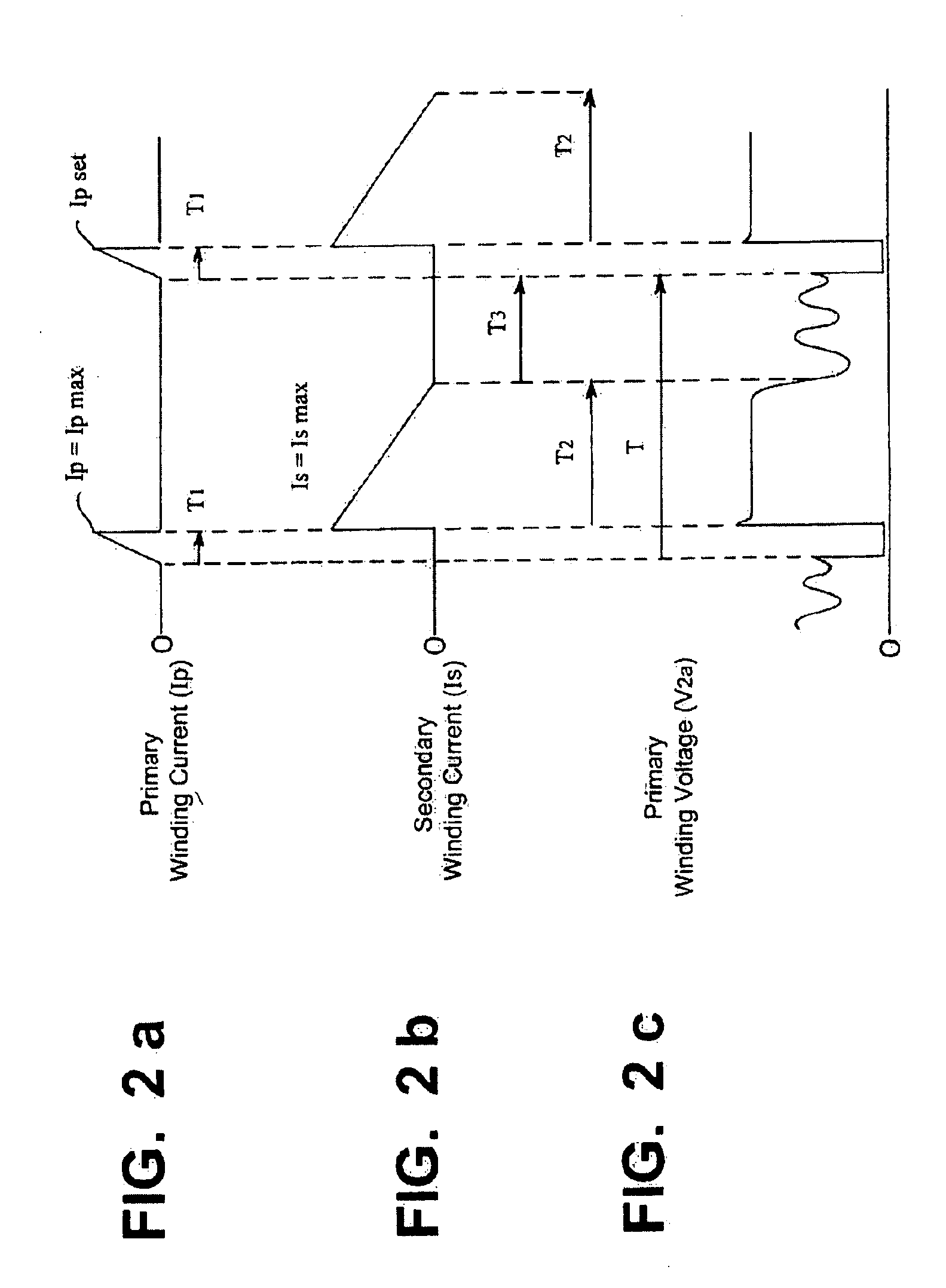
The voltage V2c generated in the auxiliary winding 2c of the transformer 2 is proportional to the voltage V2a of the primary winding 2a by a rating of the number of turns. Accordingly, once the switching device 3 is switched to OFF, the time T2 until the polarity of auxiliary winding 2...

fifth embodiment

FIG. 6 is a circuit diagram showing a constant current output control device 7 (hereinafter referred to as “switching control circuit 7”) of a switching power supply circuit 70 according to the present invention.

second embodiment

In this embodiment, the digital processing executed by the calculation circuit 5a of the switching control circuit 5, which was explained with reference to the second embodiment, is executed by the switching control circuit 7 that operates as a constant current output control device using analog processing that utilizes a comparator circuit and a logic circuit, etc.

A comparison of FIGS. 5a-5b and FIG. 6 illustrates, the structure of the switching control circuit 7 according to this embodiment is substantially the same as the structure for constant voltage output control of the switching control circuit 8 according to a previous embodiment. Accordingly, structure of the aforementioned switching power supply circuit 70 that is the same as that of the switching control circuit 8 will be denoted with the same reference numerals, and its explanation omitted. In other words, with the switching power supply circuit 70 according to this embodiment, it is possible to realize both the constan...


PUM


Abstract

A constant current output control method and device for a switching power supply circuit for constant current output control of an output current I2o of a rectifying smoothing. An OFF adjustment time T3 is:
T3=T2×(Np÷Ns×Ipref÷2÷I2oset−1)−T1  (1)
    • in which, I2oset represents a set output current of the rectifying smoothing circuit, Np represents a number of turns of a primary winding, Ns represents a number of turns of a secondary winding, T1 being a fixed time representing an ON time, Ipref representing a reference peak current flowing in the primary winding, and T2 representing an output time during which output is generated from the rectifying smoothing circuit. Output current I2o during an oscillation period T becomes set output current I2oset, and constant current output control can be executed by repeating this method.

Description

FIELD OF THE INVENTIONThe present invention relates to a constant current output control method and a constant current output control device that execute constant current output control of an output current from a secondary side of a transformer of a switching power supply circuit.BACKGROUND OF THE INVENTIONIn a switching power supply circuit such as switching regulator, an exciting current is fed to a primary winding of a transformer thus causing energy stored in the transformer to be discharged as an output of a secondary output winding. The switching power supply circuit offers a stable power supply that is compact, lightweight and highly efficient, and is therefore utilized in power supply circuits such as battery chargers and AC adapters.Conventionally, in this type of switching power supply circuit, an output voltage and current of a rectifying smoothing circuit of a secondary side are monitored such that excessively high power is not output from the rectifying smoothing circu...

Claims


Application Information

Patent Timeline
IPC IPC(8): H02M3/335H02M3/24H02M3/28
CPCH02M3/33507
Inventor AMEI, TOSHIHIRO
Owner SMK CORP
Why Eureka
Try Eureka