Combustion turbine with airfoil having enhanced leading edge diffusion holes and related methods

Inactive Publication Date: 2005-03-22
SIEMENS ENERGY INC
View PDF12 Cites 20 Cited by
  • Summary
  • Abstract
  • Description
  • Claims
  • Application Information

AI Technical Summary

Benefits of technology

In view of the foregoing background, it is therefore an object of the present invent

Problems solved by technology

Forming non-linear cooling holes may be more difficult to manufacture as compared to linear ones thereby adding to the cost of manufacturing each airfoil.
The spanwise or radial dimension of the outlet (i.e., the breakout length), for example, is usually limited by the fact that cooling holes made by electro-discharge machining or by laser

Method used


Image

  • Combustion turbine with airfoil having enhanced leading edge diffusion holes and related methods
  • Combustion turbine with airfoil having enhanced leading edge diffusion holes and related methods
  • Combustion turbine with airfoil having enhanced leading edge diffusion holes and related methods

Examples


Example

The present invention will now be described more fully hereinafter with reference to the accompanying drawings, in which preferred embodiments of the invention are shown. This invention may, however, be embodied in many different forms and should not be construed as limited to the embodiments set forth herein. Rather, these embodiments are provided so that this disclosure will be thorough and complete, and will fully convey the scope of the invention to those skilled in the art. Like numbers refer to like elements throughout.

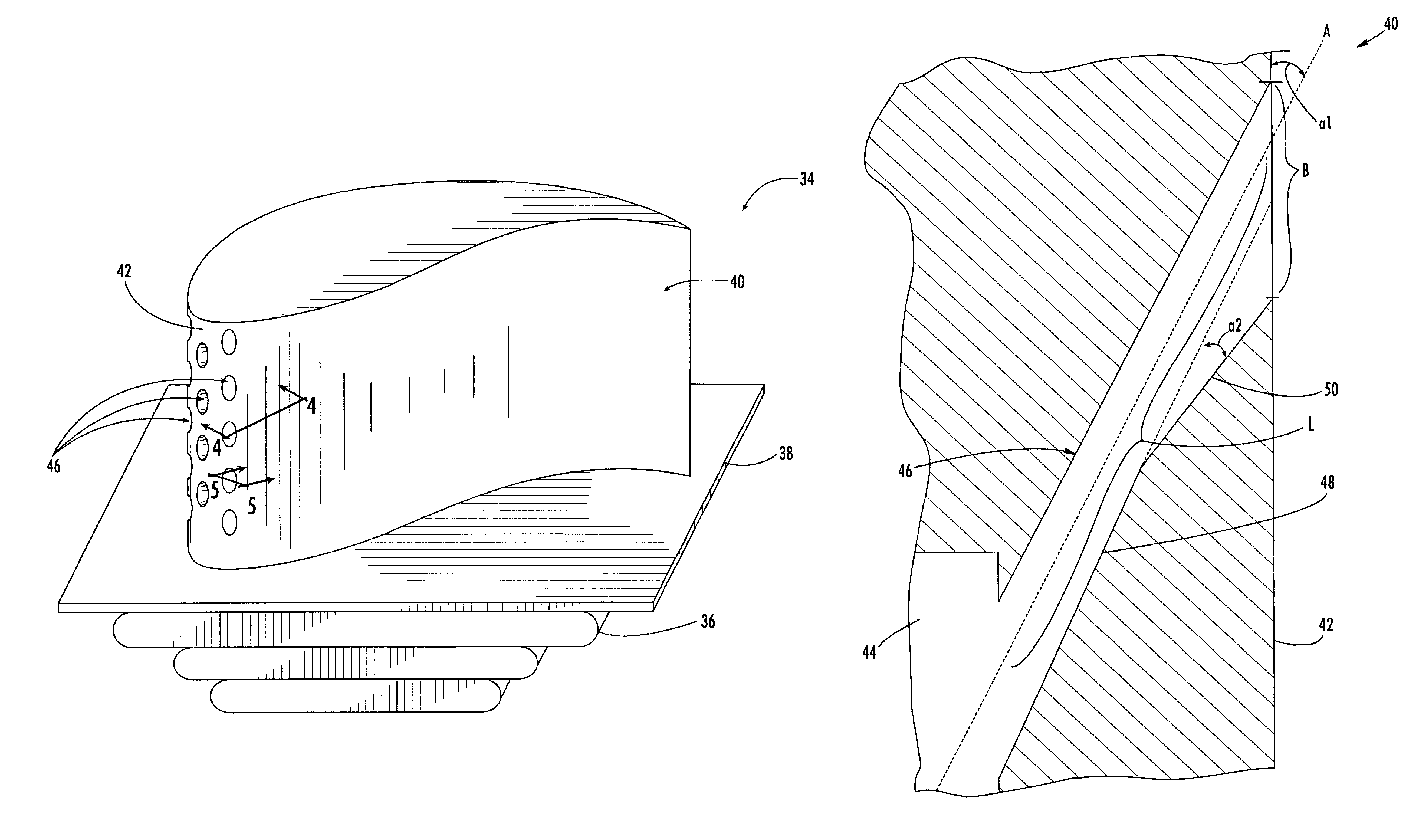
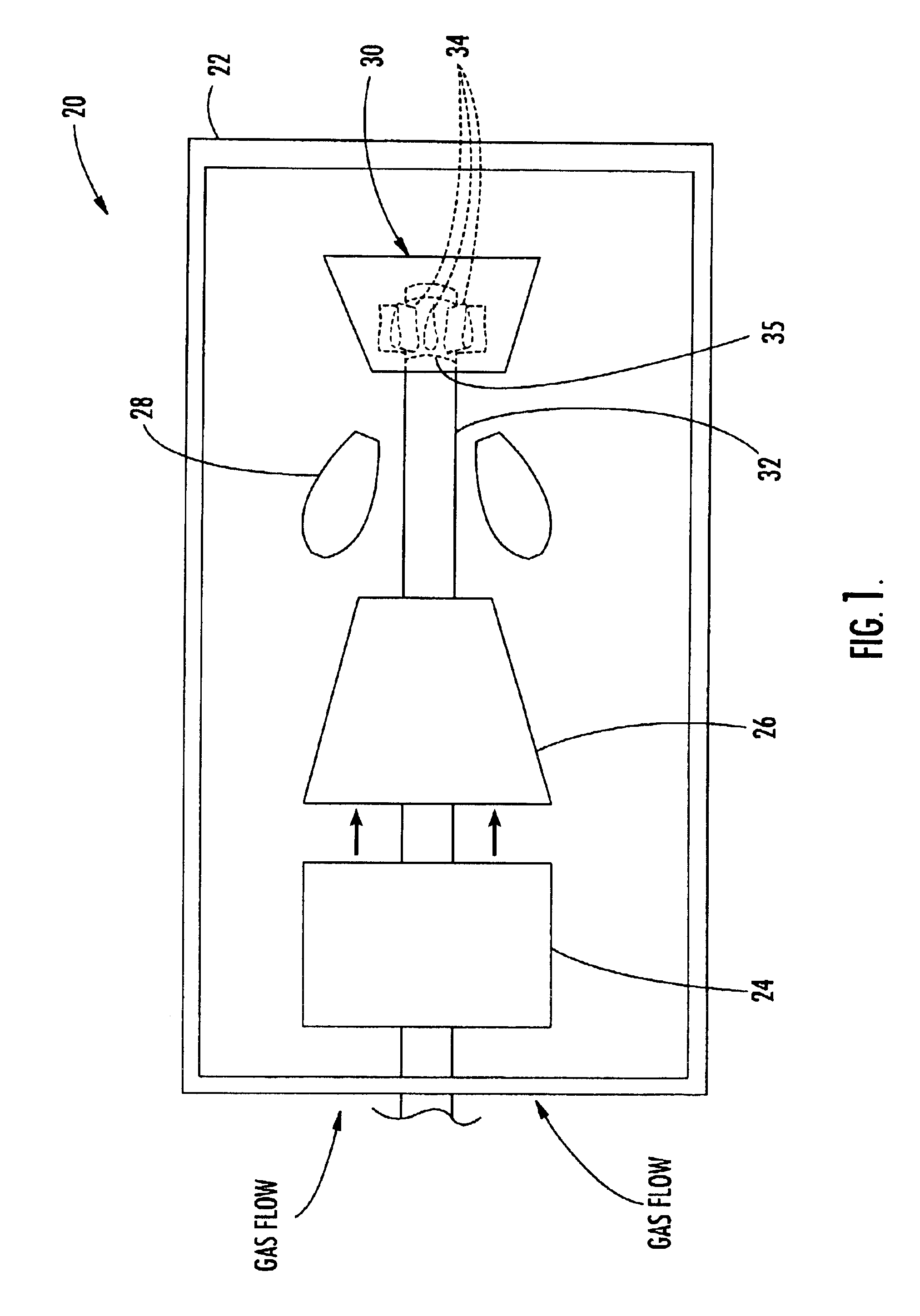
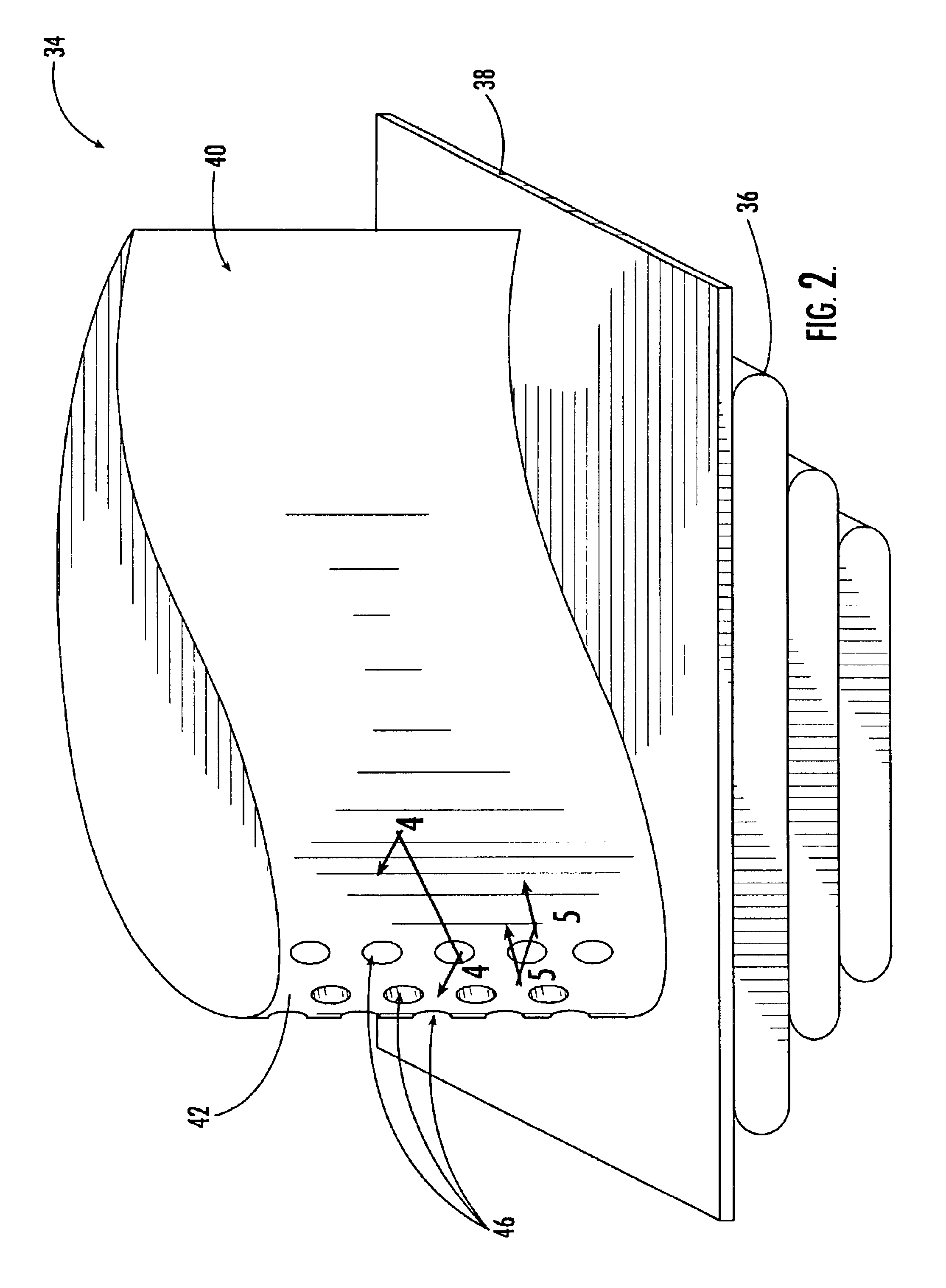
Referring initially to FIGS. 1-2, a combustion turbine 20 according to the present invention is described. The combustion turbine 20 illustratively includes a housing 22 and, within the housing, an inlet duct 24, a compressor 26 downstream from the inlet duct, a combustor 28 downstream from the compressor, and a turbine 30 downstream from the combustor. A shaft 32 illustratively extends through an upstream side of the housing 22 to the turbine 30. The combustion...


PUM


Abstract

A combustion turbine 20 includes a housing 22 and a plurality of airfoils 40 within the housing. Each airfoil 40 has a leading edge surface 42 and at least one interior cooling passageway 44. A plurality of diffusion holes 46 extend from the at least one interior cooling passageway 44 to the leading edge surface 42. Each diffusion hole 46 includes a proximal section 48 having a generally constant cross-sectional shape and a distal tapered section 50 that extends outwardly from the proximal section, tapering in a radially inward direction.

Description

FIELD OF THE INVENTIONThe present invention relates to the field of combustion turbines, and, more particularly, to combustion turbine airfoils.BACKGROUND OF THE INVENTIONA combustion turbine typically comprises a compressor to draw in and compress a gas (usually air), a combustor to add energy to the compressed gas, and a turbine driven by the resulting expansion of heated gas. The turbine, in turn, can be used to power a wide range of equipment including ships, aircraft, and power generators.The turbine typically comprises one or more stages of blade assemblies extending from a rotatable shaft and stationary guide vanes usually located adjacent the combustor. Both the blade assemblies and guide vanes typically comprise airfoils. An airfoil of a blade assembly usually extends outwardly from a platform connected to a root, which, in turn, is mounted to a turbine disk on the rotatable shaft. An airfoil of a guide vane is typically positioned between two stationary platforms. Hot gase...

Claims


Application Information

Patent Timeline
IPC IPC(8): F01D5/18
CPCF01D5/186F05D2260/202Y02T50/676Y02T50/60
Inventor LIANG, GEORGE
Owner SIEMENS ENERGY INC
Why Eureka
Try Eureka