Quartz glass jig for processing apparatus using plasma

a plasma processing and glass jig technology, applied in glass making apparatus, manufacturing tools, coatings, etc., can solve the problems of secondary adverse influence on silicon wafers, cracking of glass jigs from that portion, etc., and achieve the effect of high-quality semiconductor devices and low cos

Inactive Publication Date: 2005-03-22
HERAEUS QUARZGLAS +1
View PDF11 Cites 78 Cited by
  • Summary
  • Abstract
  • Description
  • Claims
  • Application Information

AI Technical Summary

Benefits of technology

The quartz glass jig of the invention is a jig, wherein the surface roughness Ra is from 2 μm to 0.05 μm, and the depth of the microcracks formed during the mechanical processing is 50 μm or less. When it is used as a jig for a plasma processing apparatus, abnormal etching and particles are not generated, semiconductor devices are not contaminated with impurities, and high-quality semiconductor devices can be produced at a low cost.

Problems solved by technology

But, the mechanical processing method involved a fault that simultaneously with roughening a quartz glass surface, microcracks are generated and attacked by radicals generated within the plasma, only the microcrack portion is etched and grown into an abnormal hole, and in the worst case, the quartz glass jig is cracked from that portion.
Also, recently, it has been confirmed that in the plasma, abnormally intense ultraviolet rays and electron beams are released together with ions or radicals, which deteriorate the surface of the quartz glass jig, and the deteriorated portions become a source for generating particles, leading to a secondary adverse influence on a silicon wafer.
Furthermore, it sometimes happens that impurities enter the microcracks formed by the above-described mechanical processing, and the impurities are evaporated at the treatment of a silicon wafer to contaminate the silicon wafer.

Method used


Image

  • Quartz glass jig for processing apparatus using plasma
  • Quartz glass jig for processing apparatus using plasma
  • Quartz glass jig for processing apparatus using plasma

Examples


example 1

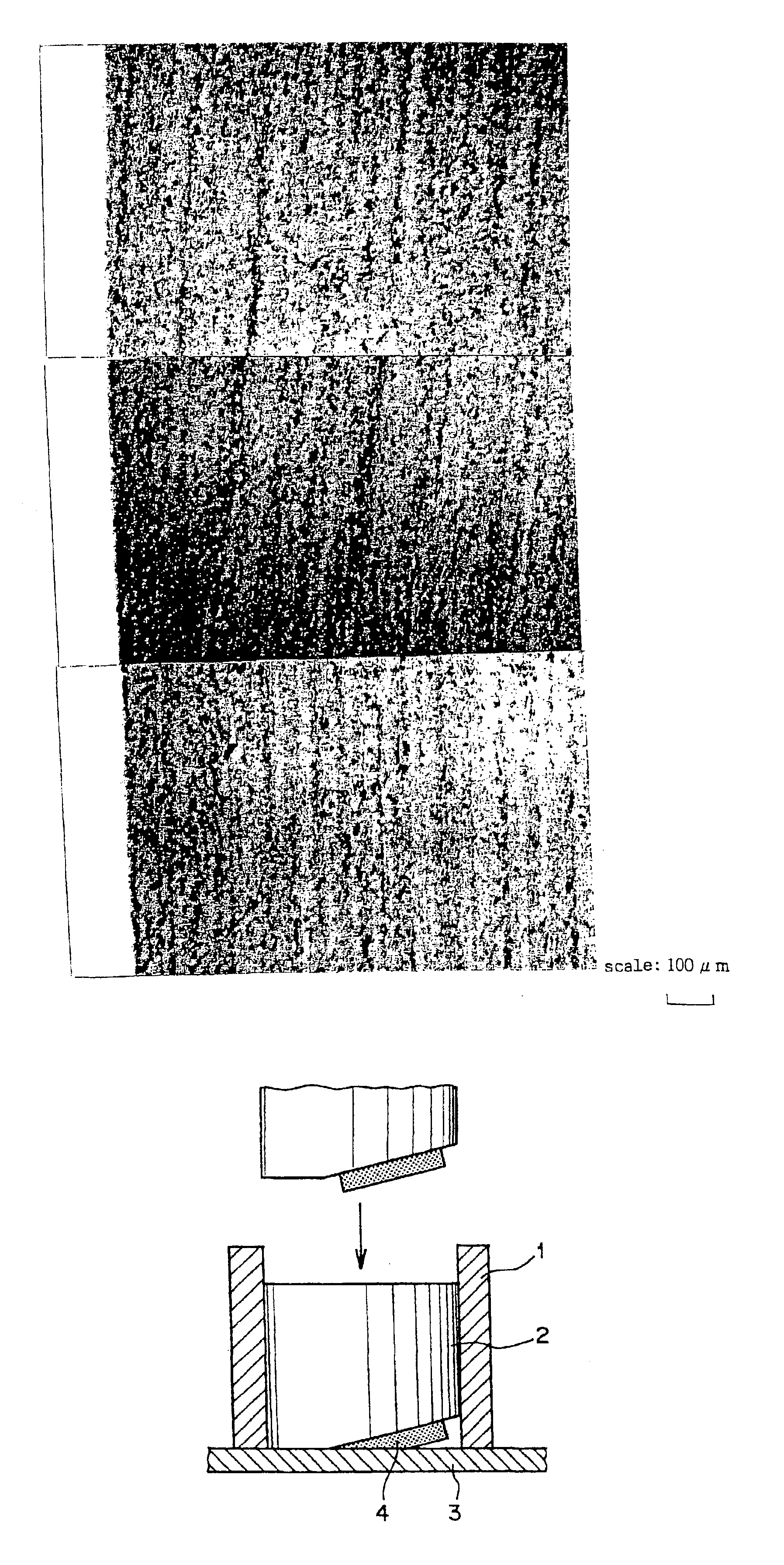
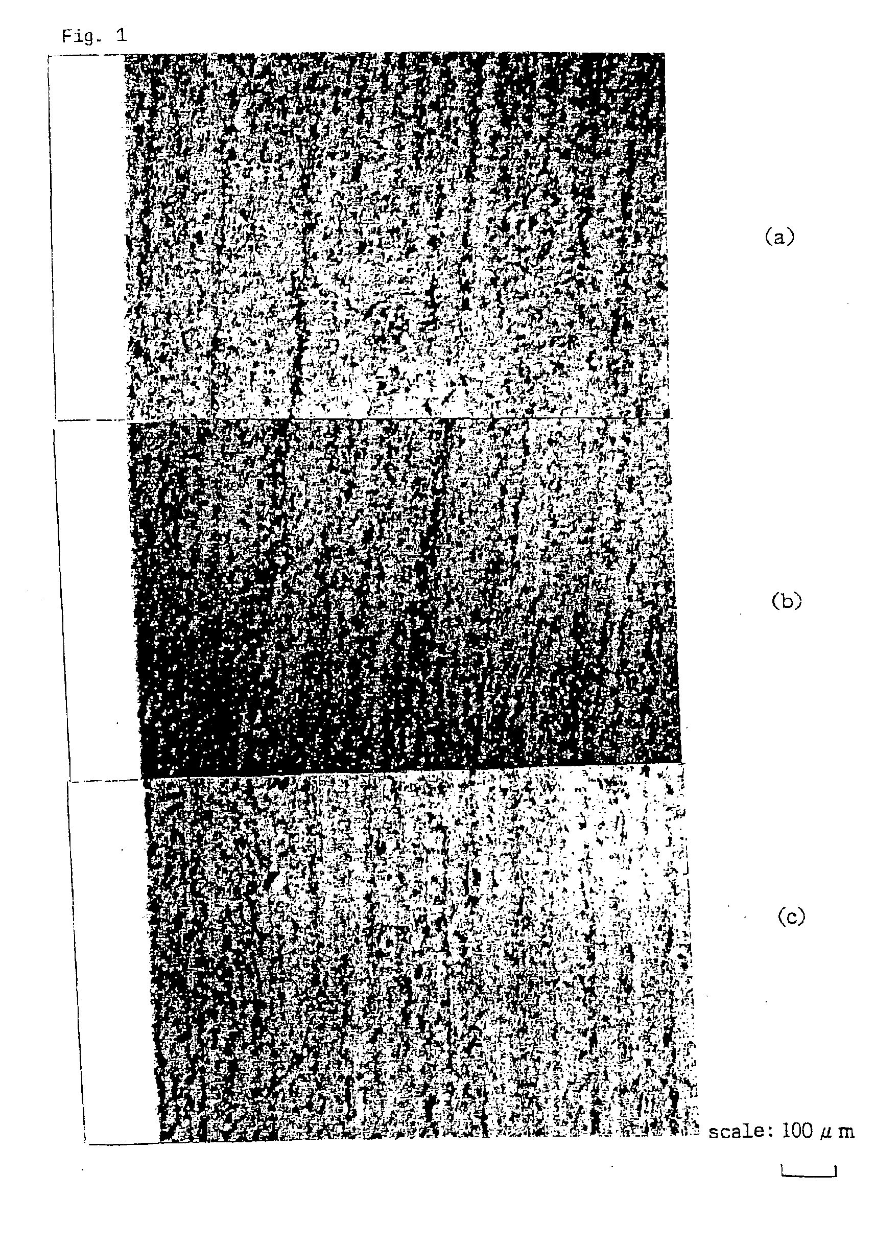
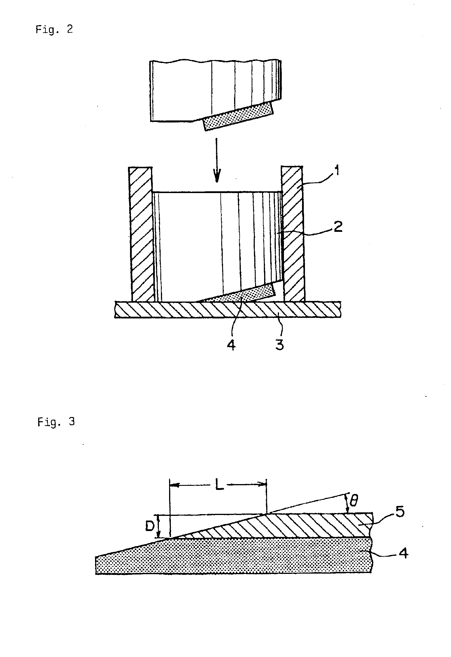
A surface of a quartz glass was processed with a whetstone made of diamond having a particle size of 100 μm to obtain a quartz glass-made ring for shielding having a surface roughness Ra of 1 μm. When the surface of this ring for shielding was observed by a microscope, 20 per millimeter of grinding marks were confirmed as shown in FIG. 1. Incidentally, FIG. 1 is a microscopic photograph of 100 magnifications of the surface of the ring for shielding described above, wherein (a) is an inner periphery side, (b) is a central portion, and (c) is an outer periphery side. With respect to a sample subjected to the same processing, after rinsing with 15% HF for 30 minutes, the sample was attached to a tip portion of a piston of a polishing apparatus shown in FIG. 2, the surface of the sample was inclined by 5° and polished to expose a microcrack layer 5 as shown in FIG. 3. A microscopic photograph at this time is shown in FIG. 4. In FIG. 4, at the right side a white portion is the portion su...

example 2

The quartz glass-made ring for shielding, wherein 200 per millimeter of the streaky grinding marks were confirmed on the surface thereof in Comparative Example 1, was subjected to sandblast processing with green carbon of #240 and then subjected to sandblast processing with green carbon of #400. Although in Comparative Example 1, the surface roughness Ra was 3 μm and the depth of the microcracks was 100 μm, after subjecting to sandblast processing with green carbon of #400, the streaky grinding marks were not observed even by a microscope. Also, the surface roughness Ra was 1.7 μm, and the depth of the microcracks was 40 μm. When this quartz glass jig was used as a ring for shielding of a plasma apparatus, after using for 3 weeks, particles were generated a little, but such was lower than that in the internal specification so that no problem was created, and the jig could be used for one month.


PUM

PropertyMeasurementUnit
surface roughnessaaaaaaaaaa
depthaaaaaaaaaa

Abstract

An object of the present invention is to provide a quartz glass jig, which, when employed in a processing apparatus using plasma, is less in generation of abnormal etching and particles and low in contamination with impurities. This object is obtained by a quartz glass jig for a processing apparatus using plasma, wherein a surface of the jig is subjected to grinding or a sandblast processing and has a surface roughness Ra in the range of from 2 μm to 0.05 μm, and microcracks of grinding marks formed during the grinding or sandblast processing have a depth of 50 μm or less.

Description

INDUSTRIAL FIELD OF APPLICATIONThe present invention relates to a quartz glass jig used in a processing apparatus utilizing plasma, and more specifically, to a quartz glass jig, wherein a surface of the quartz glass jig is roughened by mechanical processing, and the depth of microcracks formed during the mechanical processing is shallow.PRIOR ARTRecently, for the surface treatment of a semiconductor device such as a silicon wafer, etc., a treatment method utilizing plasma has bercome frequently used. As the above-described treatment method utilizing plasma, there are, for example, an etching method of introducing a halogen-based corrosive gas such as a fluorine-based gas, a chlorine-based gas, etc., in a plasma-generating chamber, while introducing a microwave via a microwave-introducing window, thereby forming a plasma from the above-described halogen-based corrosive gas internally present therein and treating a semiconductor device therewith; and a method of depositing silicon dio...

Claims


Application Information

Patent Timeline
Patent Type & Authority Patents(United States)
IPC IPC(8): C03C19/00C03C3/06H01L21/302H01L21/3065
CPCC03C3/06C03C19/00C03C2204/08
Inventor INAKI, KYOICHIWATANABE, NAOTOSEGAWA, TOHRUKIMURA, HIROYUKI
Owner HERAEUS QUARZGLAS
Why Eureka
Try Eureka