
Image transfer material with image receiving layer and heat transfer process using the same

a heat transfer process and image transfer technology, applied in the field of image transfer materials, can solve the problems of poor image quality of printed images, poor image quality, poor image quality,

Inactive Publication Date: 2005-03-22
SCHWENDIMANN JODI
View PDF53 Cites 45 Cited by
  • Summary
  • Abstract
  • Description
  • Claims
  • Application Information

AI Technical Summary

Benefits of technology

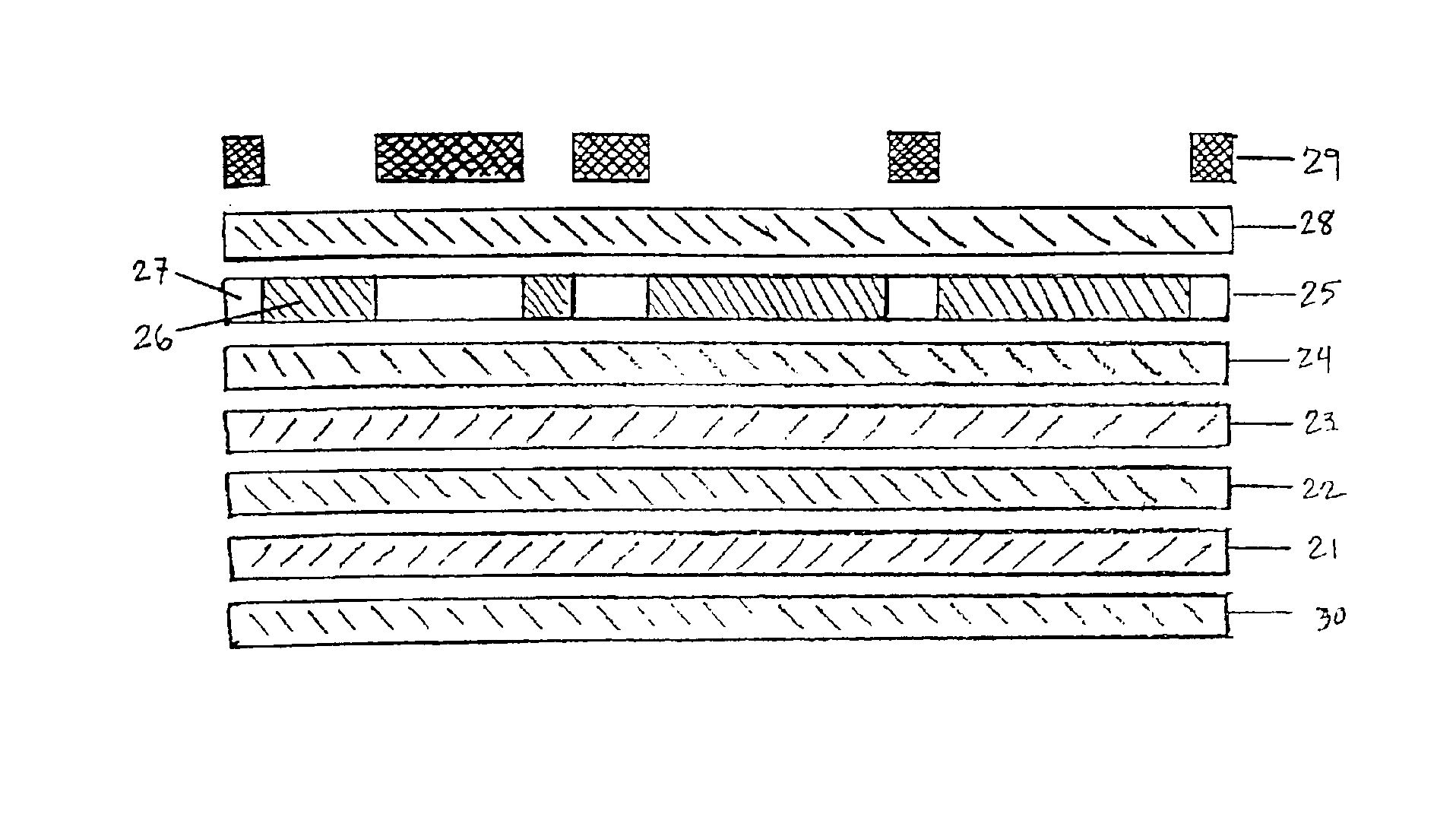
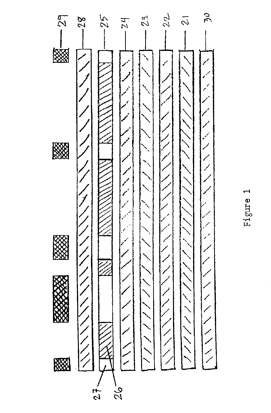
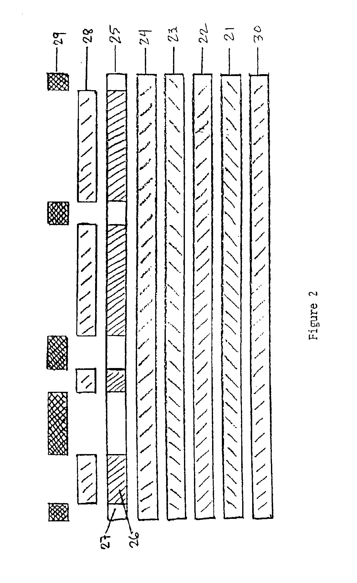
[0014]In order to attract the interest of consumer groups that are already captivated by the tee shirt rage described above, the present invention provides, in one embodiment, an improved transfer sheet. In another embodiment, the present invention provides for a process of dry heat transfer of images to receptors. A unique advantage of the present invention is that it allows for the formation of images having sharp edges, dense coloring and no mottled image areas on an image transfer element, as well as the subsequent transfer of these images onto a receptor element. The transferred image retains the sharp edges, dense coloring and absence of mottled areas of the originally formed image. Thus, the present invention enables all consumers to wear and display apparel carrying designs that were formed on the transfer material and by the process of the present invention in a timely and cost efficient manner.

Problems solved by technology

However, one problem with many known transfer sheets is poor image quality of the printed images.
Poor image quality can result when using any conventional printing process, such as, for example, ink jet printing, laser printing, lithographic offset printing, and any standard surface-to-surface printing processes.
Some examples of poor image quality include fuzzy edges, mottled image areas and / or faded images which may sometimes occur in an ink jet application of an image area onto a conventional sheet substrate.
Although such an ink boils quickly when heated to ensure rapid printing, and is not prone to clog, it results in an applied ink that is very mobile and slow to dry.
Accordingly, when these images are transferred onto a receptor element such as a T-shirt, the poor image quality is reproduced in the final product.
However, these systems are unable to solve the problem associated with poor ink / paper interaction and / or high ink absorption into the paper substrate.
Thus, the image transferred to the receptor element is flawed.

Method used


Image

  • Image transfer material with image receiving layer and heat transfer process using the same
  • Image transfer material with image receiving layer and heat transfer process using the same
  • Image transfer material with image receiving layer and heat transfer process using the same

Examples


example 1

[0285]In one embodiment of the invention, the barrier layer is a vinyl acetate polymer. An example of this embodiment is Barrier Layer Formulation 1:

Barrier Layer Formulation 1ComponentsPartsVinyl acetate-dibutyl maleate50 partspolymer dispersion (such asEVERFLEX G, HampshireChemical Corporation)Water50 parts.

[0286]Barrier Layer Formulation 1 may be prepared as follows: fifty parts of a vinyl acetate-dibutyl maleate polymer dispersion are combined with fifty parts of water by gentle stirring. The stirring is continued for approximately ten minutes at a moderate stir rate (up to but not exceeding a rate where cavitation occurs). The amount of water added may vary. The only limitation is that sufficient water is added to make the dispersion coatable on the substrate.

example 2

[0287]An example of the PMMA-containing barrier layer is Barrier Layer Formulation 2:

Barrier Layer Formulation 2ComponentsPartsAcetone 99.5%40 parts (weight)2-Propanol 99.5%40 parts (weight)PMMA20 parts (weight).

[0288]Barrier Layer Formulation 2 may be prepared as follows: The acetone and 2-propanol are weighed and mixed. The mixture is stirred. One half of the PMMA is added to the mixture while the mixture is heated to about 25° C. and stirring continues until the PMMA is dispersed. At this point, stirring continues until the remainder of the PMMA is added to the mixture and is dispersed. The mixture is then allowed to cool to room temperature.

example 3

[0289]Another example of the barrier layer of the present invention is Barrier Layer Formulation 3:

MostGeneralPreferablyPreferably(parts(parts(partsCompoundChemical Classby mass)by mass)by mass)UvacureCycloaliphatic10.0-60.020.0-50.030.0-40.01500aepoxideUvacureCycloalipahtic40.0-0.0 30.0-10.025.0-15.01562bepoxy resinDEN 431cEpoxy novolac 5.0-30.010.0-20.012.0-18.0resin2-propanolAlcohol44.4-0.0 38.3-12.430.8-21.7UvacureActivated0.5-7.01.5-6.02.0-4.01590aepoxyEbecrylaryl ketone0.1-1.00.2-0.60.2-0.5BPOaBYK 354cPolyacrylate0.0-1.00.0-0.50.0-0.4BYK 088cPolysiloxane0.0-1.00.0-0.50.0-0.4aUCB Chemical Corporation—Radcure Business Unit bDow Chemicals cBYK Chemie

[0290]Barrier Layer Formulation 3 is prepared as follows: DEN 431, an extremely viscous material, is placed into a beaker first, followed by 2-propanol. The remaining compounds are added in the order in which they appear listed in the table. Manual agitation may be required especially because of the extreme viscosity of DEN 431. Once...


PUM

PropertyMeasurementUnit
Temperatureaaaaaaaaaa
Percent by massaaaaaaaaaa

Abstract

An image transfer sheet, having a support sheet, an optional barrier layer on the support sheet, at least one heat release layer on the optional barrier layer or on the support sheet, an image receiving layer on the heat release layer, an optional image layer on the image receiving layer, an optional non-water-dispersible polymer layer on the image layer, and an optional transfer blocking overcoat layer on the optional polymer layer or the image layer, is used in a dry heat transfer process to transfer an image to a receptor element. The image receiving layer of the present invention is a precipitated calcium carbonate (PCC)-containing image receiving layer, a polyvinylpyrrolidone (PVP)-containing image receiving layer, or an image receiving layer containing both PCC and PVP (PCC / PVP).

Description

[0002]This application is a continuation of application Ser. No. 09 / 672,827, filed on Sep. 29, 2000, now abandoned which is a conversion of provisional application Nos. 60 / 220,199 filed Jul. 24, 2000 and 60 / 157,018 filed Oct. 1, 1999, the entire contents of which are hereby incorporated by reference.BACKGROUND OF THE INVENTION[0003]1. Field of the Invention[0004]The present invention relates to an image transfer material, and a process for printing images using toner, pigmented, and / or water soluble colorants from a heat transferable material having an image receiving layer, which image receiving layer contains 1) precipitated calcium carbonate (PCC), 2) polyvinylpyrrolidone (PVP), or 3) a combination of PCC and PVP (PCC / PVP). More specifically, the present invention relates to an image transfer sheet which can be applied to a receptor element, such as cotton or cotton / polyester blend fabrics or the like.[0005]2. Description of the Prior Art[0006]Textiles such as shirts (e.g., tee s...

Claims


Application Information

Patent Timeline
IPC IPC(8): G03G15/01G03G7/00B41M5/025B41M5/00B41M5/52
CPCG03G7/0013G03G7/0033G03G7/0046G03G15/0152G03G15/0163G03G7/004B41M5/0256B41M5/5254Y10T428/24802G03G2215/017
Inventor WILLIAMS, SCOTT A.AGLER, ANNE HERMETET
Owner SCHWENDIMANN JODI
Learn More