Method and apparatus for controlling acceleration and velocity of a stepper motor

a stepper motor and acceleration technology, applied in the direction of electric programme control, dynamo-electric converter control, instruments, etc., can solve the problem of inability to achieve a precise target velocity, the rotor may not rotate at all, and the step loss to the extent that the rotor cannot be precisely calculated with precision, etc., to achieve the effect of improving the start-stop velocity control, less expense, and similar operating characteristics

Inactive Publication Date: 2005-03-22
MIND FUSION LLC
View PDF8 Cites 23 Cited by
  • Summary
  • Abstract
  • Description
  • Claims
  • Application Information

AI Technical Summary

Benefits of technology

It is another object of the present invention to provide such a method and apparatus which has improved start-stop velocity control.
It is another object of the present invention to provide such a method and apparatus which has similar operating characteristics to a DC servomotor with substantially less expense.
However, according to the present invention, surprisingly, it has been found experimentally that the maximal motor shaft velocity can be much more than 10,000 half steps per second. In the proposed invention, the increase of the driving force and the extension of the range of steady-state movement has been achieved for advanced motor coils commutation with constant frequency using velocity feed back and gradual step-wise phase shifting where the phase offset is selected depending on rotor velocity.

Problems solved by technology

In such open-loop configurations, if the load is different than that for which the commutation sequence was developed, steps can be lost to the extent that the rotor may not rotate at all.
While the motor does not lose steps with this method, it cannot achieve a precise target velocity due to uncontrollable variance in parameters such as motor supply voltage, friction, etc.
Moreover, when a desired velocity is selected, the corresponding switching angle typically cannot be calculated with precision.
The drawback of this technique is electrical power loss in the resistor;electrical damping by spooling an additional coil together with the main coil.
The drawbacks of the method is power reduction and increase in motor' moment of inertia;high-voltage feeding of a winding until the required current appears.
The drawback is increase in power loss and the complexity of driving circuitry.
The foregoing prior art stepper motor systems will not accurately control the velocity and position of a load during the acceleration and deceleration periods and experience substantial power losses and temperature increase which imposes limitations on operation characteristics of the motor.

Method used


Image

  • Method and apparatus for controlling acceleration and velocity of a stepper motor
  • Method and apparatus for controlling acceleration and velocity of a stepper motor
  • Method and apparatus for controlling acceleration and velocity of a stepper motor

Examples


Embodiment Construction

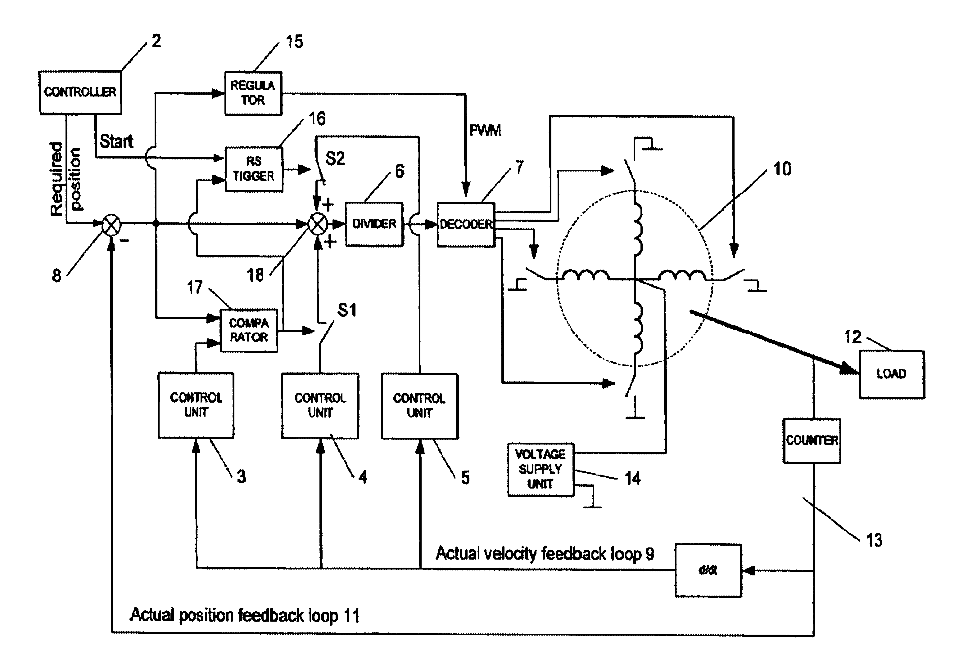
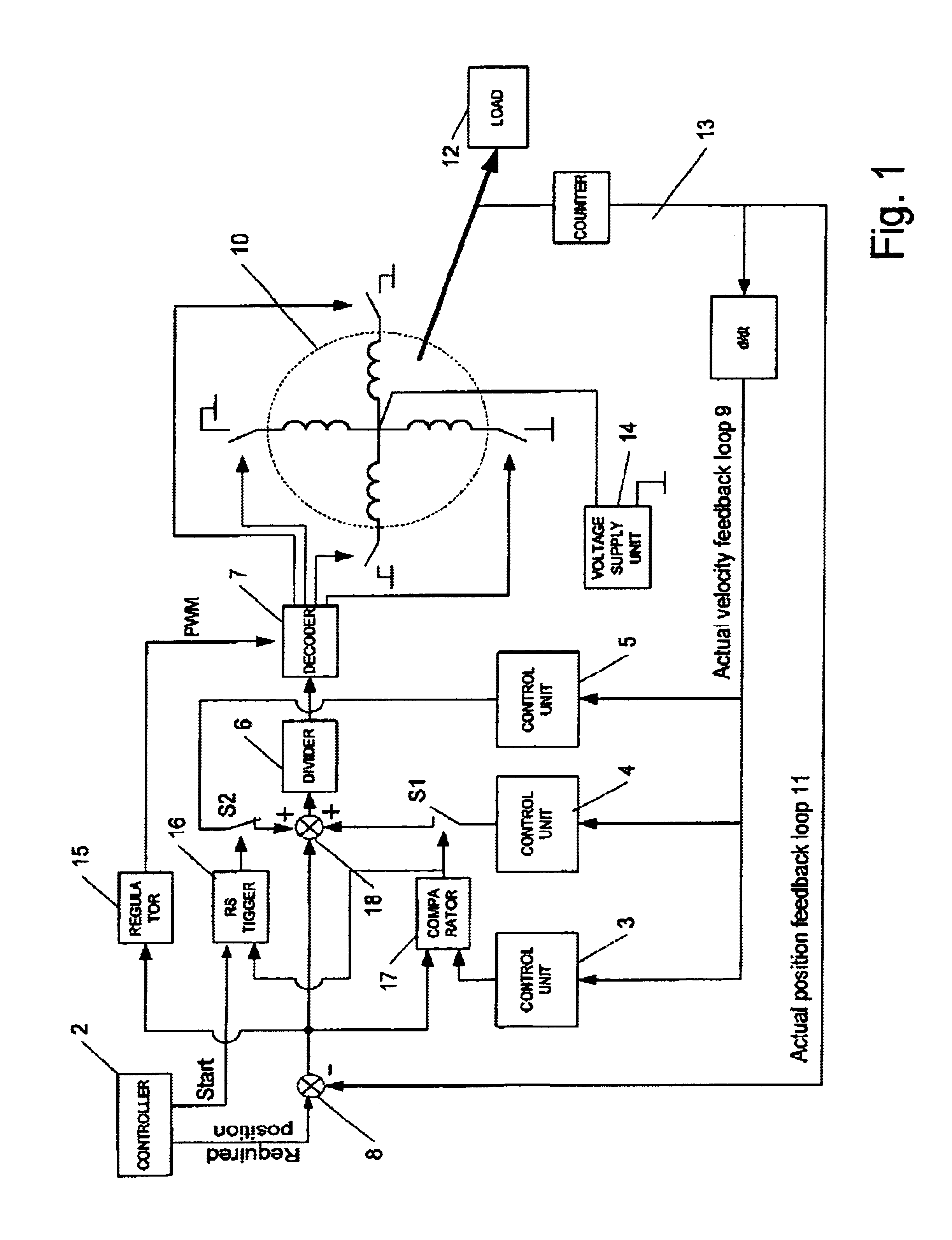
FIG. 1 illustrates a stepper motor control circuit constructed in accordance with the present invention. A stepper motor 10 is connected to a load 12. The stepper motor 10 control circuit includes a computer / controller 2, comparators 817 for comparing the expected and actual sensor data, summator 18, divider 6 for providing a count representative of a desired position of the shaft of the motor, decoder 7 for determining the current phase to be energised and a conventional circuitry including regulator 15, RS trigger 16, switches S2 and S1, and voltage supply unit 14. All the above mentioned comparators and summators may be implemented as conventional FPGA (field programmable gate arrays) which may be easily selected by a specialist in the art from electronic components available in the market. In the present example, stepper motor 10 is a 4-phase hybrid stepper motor, such as characterised in Table 1.

TABLE 1Stepper motor example characteristicsRated voltageV12Rated currentA0.6Resist...


PUM


Abstract

A method and apparatus for controlling acceleration and velocity of a stepper motor in which a phase offset is selected depending on motor velocity. The optimal phase offset indicates the position of the winding which generates the maximal driving moment. The increase of the driving force and the extension of the range of steady-state movement is achieved for advanced motor coils commutation with constant frequency using velocity feed back and gradual step-wise phase shift where the phase offset is selected depending on rotor velocity. The invention may be effectively applied to servomotors, stepper motors, motors having certain limitations on movement parameters, such as limitations on acceleration and other types of motors.

Description

BACKGROUND OF THE INVENTIONThe present invention relates to methods and apparatus for controlling acceleration and velocity of a stepper motor and more particularly to such methods and apparatus in which the stepper motor switching angle varies.Stepper motors transfers with high accuracy digital electrical signals directly into discreet angle movements (steps) of a rotor. Stepper motors are synchronous motors in which rotor's positions depends directly on driving signal. Rotary moment is defined by magnetic energy and is proportional to the tooth number of the rotor.Most stepper motors are operated in an open-loop configuration. Given a known and fixed load driven by the stepper motor, a commutation (step) sequence can be developed by a person having ordinary skill in the art which accelerates the load to a desired velocity without a loss of steps. In other words, each time the motor is commutated, the rotor is in a position in which torque generated by the electrical field advances...

Claims


Application Information

Patent Timeline
Patent Type & Authority Patents(United States)
IPC IPC(8): H02P8/22H02P8/14H02P8/04
CPCH02P8/04H02P8/22H02P8/14
Inventor DAVIDOV, VLADIMIR NIKOLAYEVICH
Owner MIND FUSION LLC
Why Eureka
Try Eureka