Apparatus and method for determining tissue characteristics

a tissue characteristic and apparatus technology, applied in the field of apparatus and methods for determining tissue characteristics of patients, can solve the problems of high cost of these components, limited accuracy of measurements made by these methods, and inability to use these techniques in typical clinical settings, so as to reduce or eliminate cross-talk and improve resolution

Inactive Publication Date: 2005-03-22
SPECTRX
View PDF27 Cites 65 Cited by
  • Summary
  • Abstract
  • Description
  • Claims
  • Application Information

AI Technical Summary

Benefits of technology

An instrument as described above could be configured to allow rotation of the optical fibers between a plurality of predetermined rotational positions. One embodiment could be configured so that the optical fibers are located at a series of unique positions as the optical fibers are rotated between the predetermined rotational positions. This would allow the device to capture multiple readings at a large number of unique positions on the target tissue. Such a multiple cycle measurement process would allow the optical fibers to be spaced far enough apart to reduce or eliminate cross-talk, while still providing greater resolution than would be possible with a single measurement cycle.

Problems solved by technology

It is known that the accuracy of measurements made by these methods is limited by practical issues such as variation in lamp intensity and changes in fluorophore concentration.
Unfortunately, these methods require expensive components that are capable of generating extremely short bursts of excitation light, and that are capable of recording the relatively faint fluorescent emissions that occur over time.
The high cost of these components has prevented these techniques from being used in typical clinical settings.

Method used


Image

  • Apparatus and method for determining tissue characteristics
  • Apparatus and method for determining tissue characteristics
  • Apparatus and method for determining tissue characteristics

Examples


Embodiment Construction

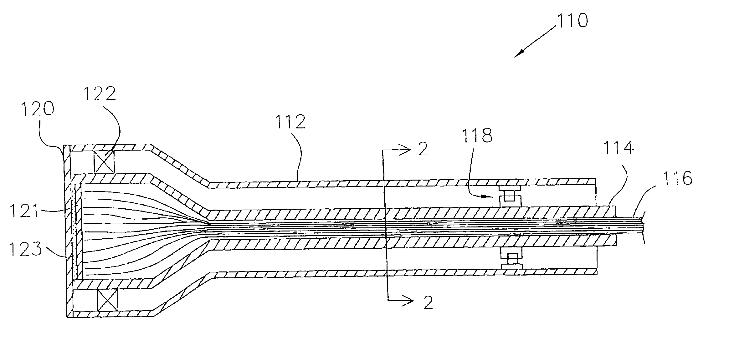
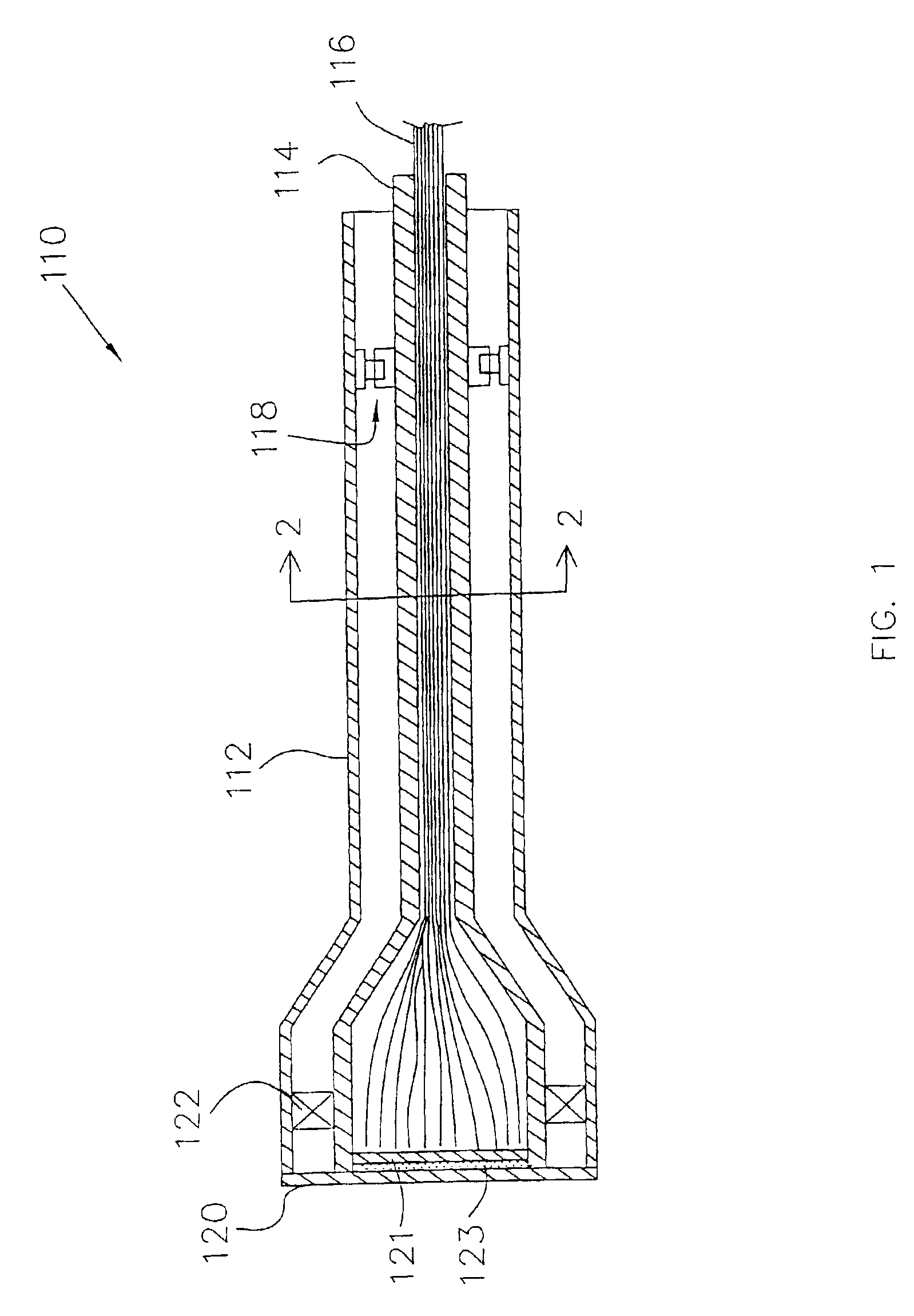
The invention is primarily concerned with devices which are used to take measurements on a target material or tissue. Devices embodying the invention are capable of conforming to nonplaner tissue so that accurate spectroscopic based measurements can be taken.

Devices and method embodying the invention can utilize a wide range of different spectroscopic interrogation techniques to detect or diagnose the condition of a target material or tissue. For instance, a device embodying the invention could be configured to take reflectance or scattering measurements, or measurements of fluorescence produced by a target material or tissue. The fluorescence measurements could include measurements of the amplitude of particular wavelengths, or measurements of the lifetime of a fluorescent emission. Furthermore, a scattering measurement, or a fluorescence measurement, could be conducted using phase shift or a polarization anisotropic method. Some of the many different types of spectroscopic interro...


PUM

PropertyMeasurementUnit
diameteraaaaaaaaaa
diameteraaaaaaaaaa
wavelengthsaaaaaaaaaa

Abstract

An apparatus embodying the invention includes a probe head with an interrogation surface that is intended to be positioned adjacent or pushed into contact with a target material or tissue. The probe head is constructed to have a plurality of interrogation devices arranged across the face of the interrogation surface. The probe head is also constructed so that the interrogation device can conform to a non-uniform or non-planar surface of the target tissue. In some embodiments, the interrogation surface may have a particular shape that conforms to the shape of a target material. In other embodiments, one or more portions of the interrogation surface could be movable with respect to the remaining portions so that the interrogation surface could be movable with respect to remaining portions so that the interrogation surface can thereby conform to a non-uniform surface. In still other embodiments, a plurality of separately moveable interrogation devices can be arranged across the interrogation surface. During a measurement process, the interrogation surface would be pressed into contact with the non-uniform surface to cause individual ones of the interrogation devices to move, thereby causing the probe head to conform to the non-uniform surface.

Description

BACKGROUND OF THE INVENTION1. Field of the InventionThe invention is related to apparatus and methods for determining characteristics of a target tissue of a patient.2. Background of the Related ArtIt is known to irradiate a target tissue with electromagnetic radiation and to detect returned electromagnetic radiation to determine characteristics of the target tissue. In known methods, the amplitudes and wavelengths of the returned radiation are analyzed to determine characteristics of the target tissue. For instance, U.S. Pat. No. 4,718,417 to Kittrell et al. discloses a method for diagnosing the type of tissue within an artery, wherein a catheter is inserted into an artery and excitation light at particular wavelengths is used to illuminate the interior wall of the artery. Material or tissue within the artery wall emits fluorescent radiation in response to the excitation light. A detector detects the fluorescent radiation and analyzes the amplitudes and wavelengths of the emitted f...

Claims


Application Information

Patent Timeline
Patent Type & Authority Patents(United States)
IPC IPC(8): A61B5/00G01N21/47G01N21/64G01N21/49G01N21/21
CPCA61B5/0059A61B5/0084A61B5/6843G01N21/474A61B5/4331A61B5/0071A61B5/0075A61B5/0091G01N21/64A61B2562/164G01N21/21G01N21/49
Inventor FAUPEL, MARK L.BAMBOT, SHABBIR B.HARRELL, TIMFARQUHAR, J. DAVIDARCHE, GLENN S.SANDERS, WALTER R.KIMBRELL, EDWARD L.
Owner SPECTRX
Why Eureka
Try Eureka