Fluorescence Lifetime Well Array Reader and Actuator

Pending Publication Date: 2021-09-23
CHARLES STARK DRAPER LABORATORY
View PDF0 Cites 0 Cited by
  • Summary
  • Abstract
  • Description
  • Claims
  • Application Information

AI Technical Summary

Benefits of technology

The patent is about a machine that can monitor the process of amplifying DNA using a technique called polymerase chain reaction (PCR) by measuring the change in fluorescent light produced during the reaction. The machine uses special dyes that change their fluorescence as the DNA is copied. By measuring the time-related changes in the light, the machine can track the progress of the reaction and compare different dyes or light sources. The modulation frequencies used for the light can be adjusted to minimize cross-talk and bleaching, and the machine can measure the properties of the DNA molecule independently of the overall light intensity. The machine is designed to be compact and cost-effective, with a printed circuit board and optical block for interfacing to the well array. The technical effects are improved accuracy and sensitivity in measuring PCR reactions and the ability to compare different dyes or light sources.

Problems solved by technology

They also do not allow for multiple wavelengths of light to be targeted at the wells on a per-well basis, with illumination patterns controlled on a per well basis.
However, the increased or decreased fluorescent intensity is almost always accompanied by a significant change in the radiative lifetime of the fluorescent dye.

Method used


Image

  • Fluorescence Lifetime Well Array Reader and Actuator
  • Fluorescence Lifetime Well Array Reader and Actuator
  • Fluorescence Lifetime Well Array Reader and Actuator

Examples


Embodiment Construction

[0043]The invention now will be described more fully hereinafter with reference to the accompanying drawings, in which illustrative embodiments of the invention are shown. This invention may, however, be embodied in many different forms and should not be construed as limited to the embodiments set forth herein; rather, these embodiments are provided so that this disclosure will be thorough and complete, and will fully convey the scope of the invention to those skilled in the art.

[0044]As used herein, the term “and / or” includes any and all combinations of one or more of the associated listed items. Further, the singular forms and the articles “a”, “an” and “the” are intended to include the plural forms as well, unless expressly stated otherwise. It will be further understood that the terms: includes, comprises, including and / or comprising, when used in this specification, specify the presence of stated features, integers, steps, operations, elements, and / or components, but do not pre...


PUM

PropertyMeasurementUnit
Lifetime stabilityaaaaaaaaaa
Speedaaaaaaaaaa
Fluorescenceaaaaaaaaaa

Abstract

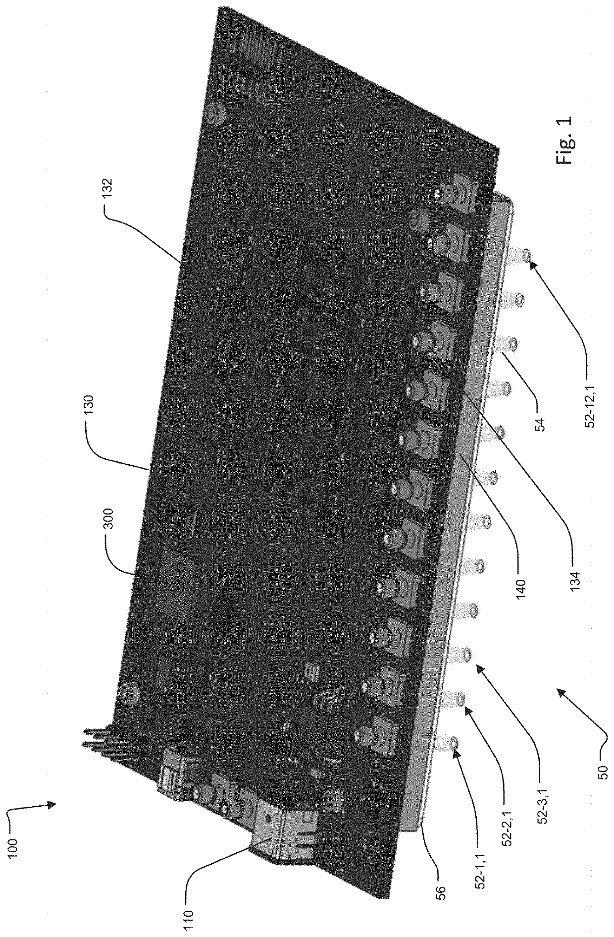
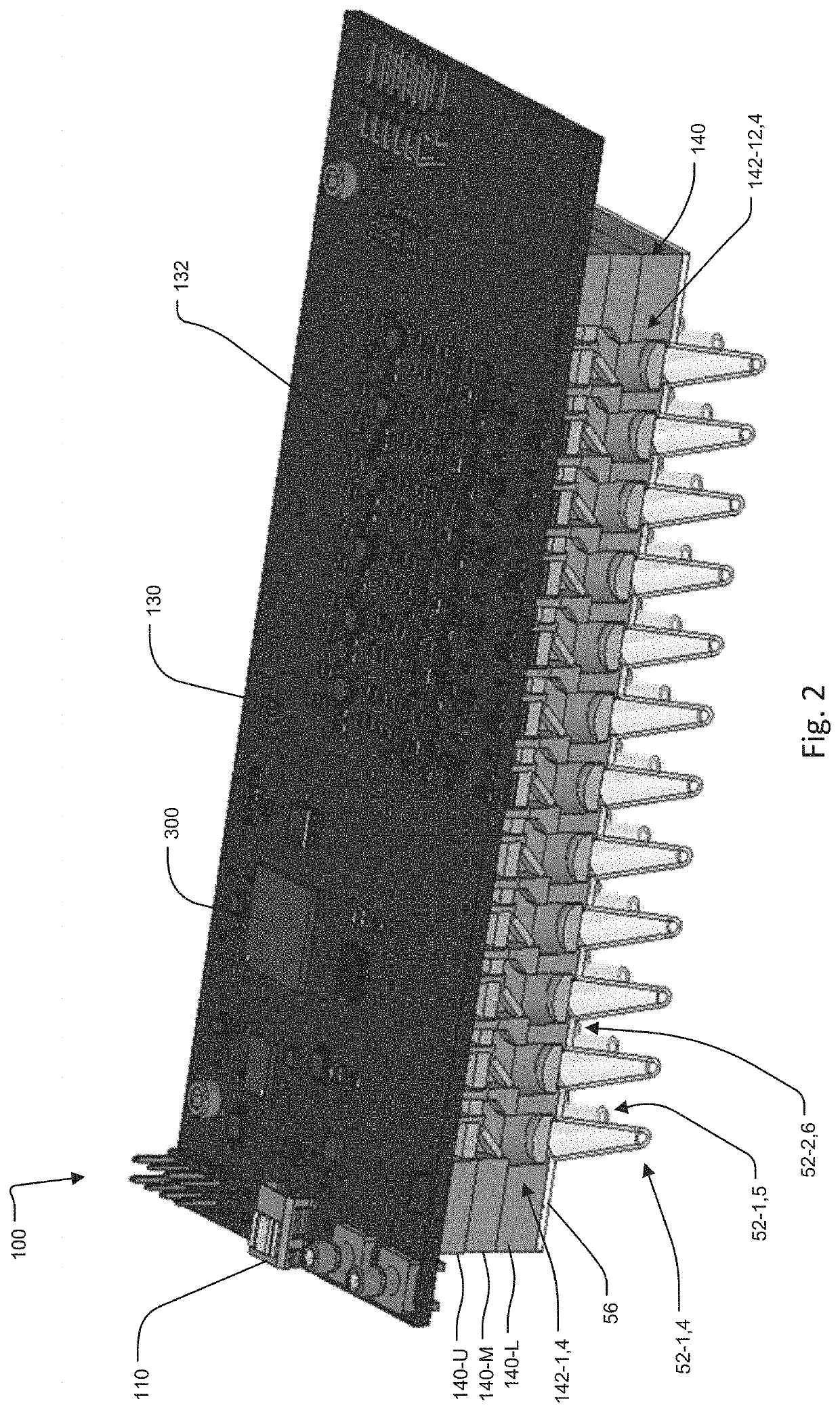
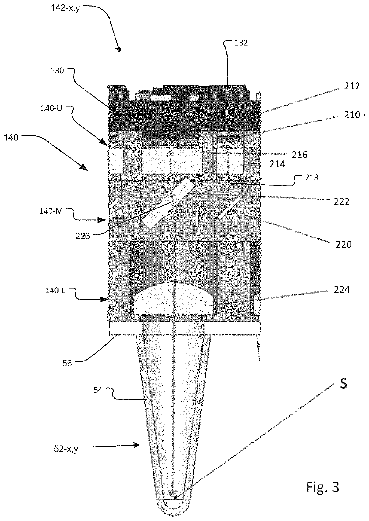
A well reader and actuator (100) for a well array (50) has an array of detectors, each detector for detecting a fluorescence signal from fluorophores in a respective well of the well array and an excitation subsystem for exciting the fluorophores in the wells of the well array. Embodiments of this invention can be used to carry out two important functions in a highly parallel manner: by addressing individual wells in a 32, 96, 384 etc. well array, where each well contains a potential chemical or biological reaction. The two functions are: 1) through thermal, optical or other means and combinations thereof the rate of a chemical or biological reaction is controlled or gated (e.g. colder wells inhibit a reaction, or an enzymatic reaction requires blue light to proceed); and 2) through use of fluorescent species that are sensitive to the target reaction—or reactions—an optical readout of fluorescent intensity and / or lifetime is tracked to monitor the evolution of the reaction.

Description

RELATED APPLICATIONS[0001]This application claims the benefit under 35 USC 119(e) of U.S. Provisional Application No. 62 / 713,807, filed on Aug. 2, 2018, which is incorporated herein by reference in its entirety.BACKGROUND OF THE INVENTION[0002]Well arrays are used as large sets of small test tubes in analytical research and clinical diagnostic testing. A common example of a well array is a microplate or microwell plate. These are flat plates with multiple wells. Another example is “Eppendorf” or microcentrifuge tube rack. Here, a set of tubes are held in a rack for convenience and running a large number of separate tests. Well arrays also come in various sizes. The most common well array format is the 96-well array in an 8 by 12 matrix. Larger arrays such as 384- or 1536-well arrays are also available.[0003]Plate readers are instruments that are used to detect biological, chemical or physical events associated with samples in the well arrays. They are widely used in research, drug d...

Claims


Application Information

Patent Timeline
IPC IPC(8): G01N21/64C12Q1/686B01L3/00
CPCG01N21/6408G01N21/6454G01N21/6486B01L2300/0832B01L3/5085B01L2300/0829C12Q1/686G01N2021/6419B01L7/52B01L9/523B01L3/50851C12Q2561/113C12Q2563/173
Inventor FRANK, IAN W.MAGYAR, ANDREW P.LARSEN, CORYUNG, JONATHAN S.RUSSELL, KASEY J.MCFARLAND, KIRSTY A.KORN, JEFFREY A.
Owner CHARLES STARK DRAPER LABORATORY
Why Eureka
Try Eureka