Projection zoom lens system and projector

a technology of projection zoom and projector, which is applied in the field of projection zoom lens system, can solve the problems of inability to provide a compact lens system, inability to zoom or variable-power lenses, etc., and achieve the effect of favorable image forming performance and favorable correction of aberrations

Inactive Publication Date: 2005-03-22
NITTO OPTICAL CO LTD
View PDF7 Cites 26 Cited by
  • Summary
  • Abstract
  • Description
  • Claims
  • Application Information

AI Technical Summary

Benefits of technology

In the projection zoom lens system of the present invention, the fourth lens group acts as a compensator and even if the fourth lens group moves to compensate aberrations during zooming, the distance moved is so small. This means that the moving distance of the position of the entrance pupil, into which the projection light enters from the light modulator via the field lens, is small. Accordingly, it is possible to provide a projection zoom lens system that is suited to a reflective-type light modulator such as a DMD and can efficiently take in the projection light from such light modulator and project a bright image. On the other hand, the fourth lens group can move a minute distance as a compensator during zooming, it makes the projection zoom lens system to have favorable compensating of aberrations during zooming and to have superior image forming performance. This means that by using the projection zoom lens system of the present invention, it is possible to provide a projector apparatus that can display bright and clear images, is compact, is equipped with a zoom function, and uses a light modulator, such as a DMD, equipped with elements that form an image by changing the directions of reflection of light.
In order to improve the aberration performance of the projection zoom lens system with a construction using small number of lenses, it is preferable to introduce one or more aspherical lenses. In the projection zoom lens system of the present invention, the first, second and fourth lens groups do not move, or move by only a short distance, so that there is little fluctuation in the transmitted rays during zooming. Accordingly, it is easy to design the aspherical lens(es), and the aberration performance can be further improved by introducing an aspherical lens or lenses into at least one or a plurality of the first, second, and fourth lens groups.
Out of the first, second, and fourth lens groups, in the first lens group that is closest to the screen, the rays of the image near or around the optical axis pass close to the center of the lens(es), with the rays of the image near or around the periphery passing the periphery of the lens(es). In addition, in a compact zoom lens system, lenses of the first lens group have the greatest diameters. Accordingly, the rays that pass the lens center and lens periphery are different and have some distance, so that the aberration correcting effect of an aspherical surface is great. By providing an aspherical surface or surfaces in the first lens group, it is possible to correct mainly astigmatism, curvature of field, and distortion. In addition, by providing an aspherical surface or surfaces in the fourth lens group, it is possible to correct mainly spherical aberration and coma aberration, so that the lens system in which aberrations are corrected even more favorably can be provided.
In order to favorably correct aberrations such as astigmatism, the traveling distance greater than the lower limit shown in Equation (B) above is needed, and in a zoom lens system with a zoom ratio of 1.25, this distance is around 3.8 mm. As the upper limit, the traveling distance of the fourth lens group can be suppressed to around 5 mm or below. Accordingly, it is possible to provide a zoom lens with the field lens and favorable image forming performance where various aberrations are corrected with the position of the entrance pupil hardly moving during zooming.

Problems solved by technology

This means that the lens group positioned on the screen side of the field lens cannot be a zooming or variable-power lens group.
Accordingly, if this lens group moves during zooming, it becomes necessary to simultaneously perform focusing and zooming, so that the mechanism becomes complex and it is not possible to provide a compact lens system.

Method used


Image

  • Projection zoom lens system and projector
  • Projection zoom lens system and projector
  • Projection zoom lens system and projector

Examples


first embodiment

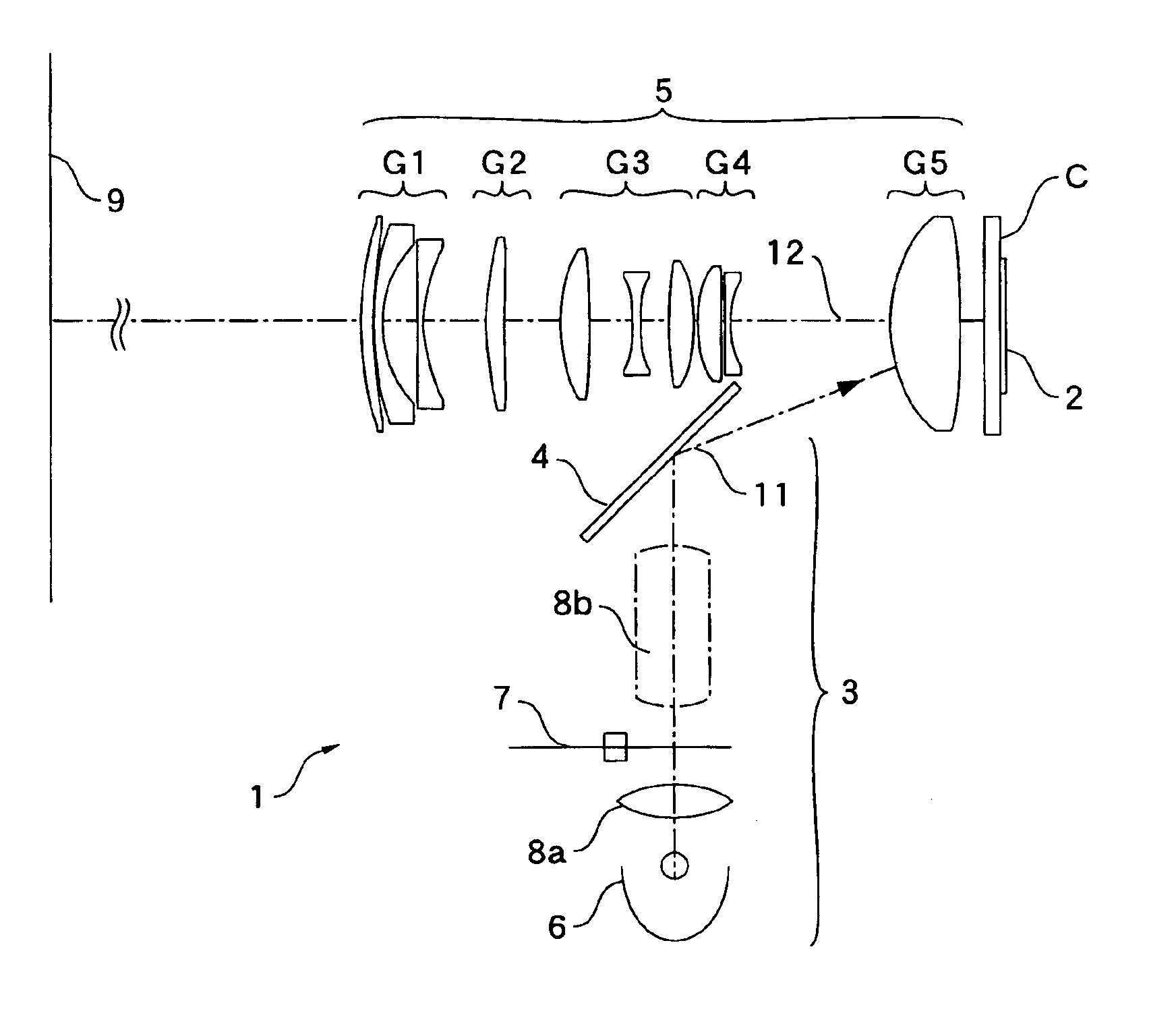
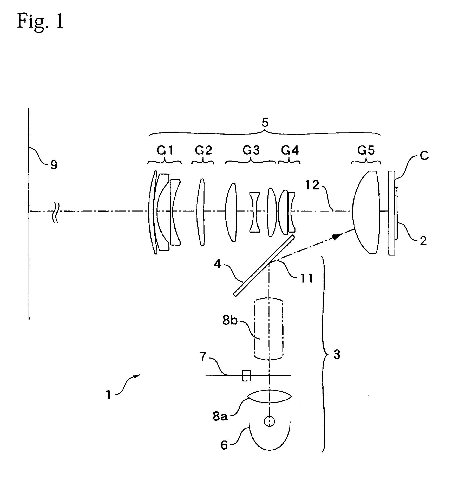
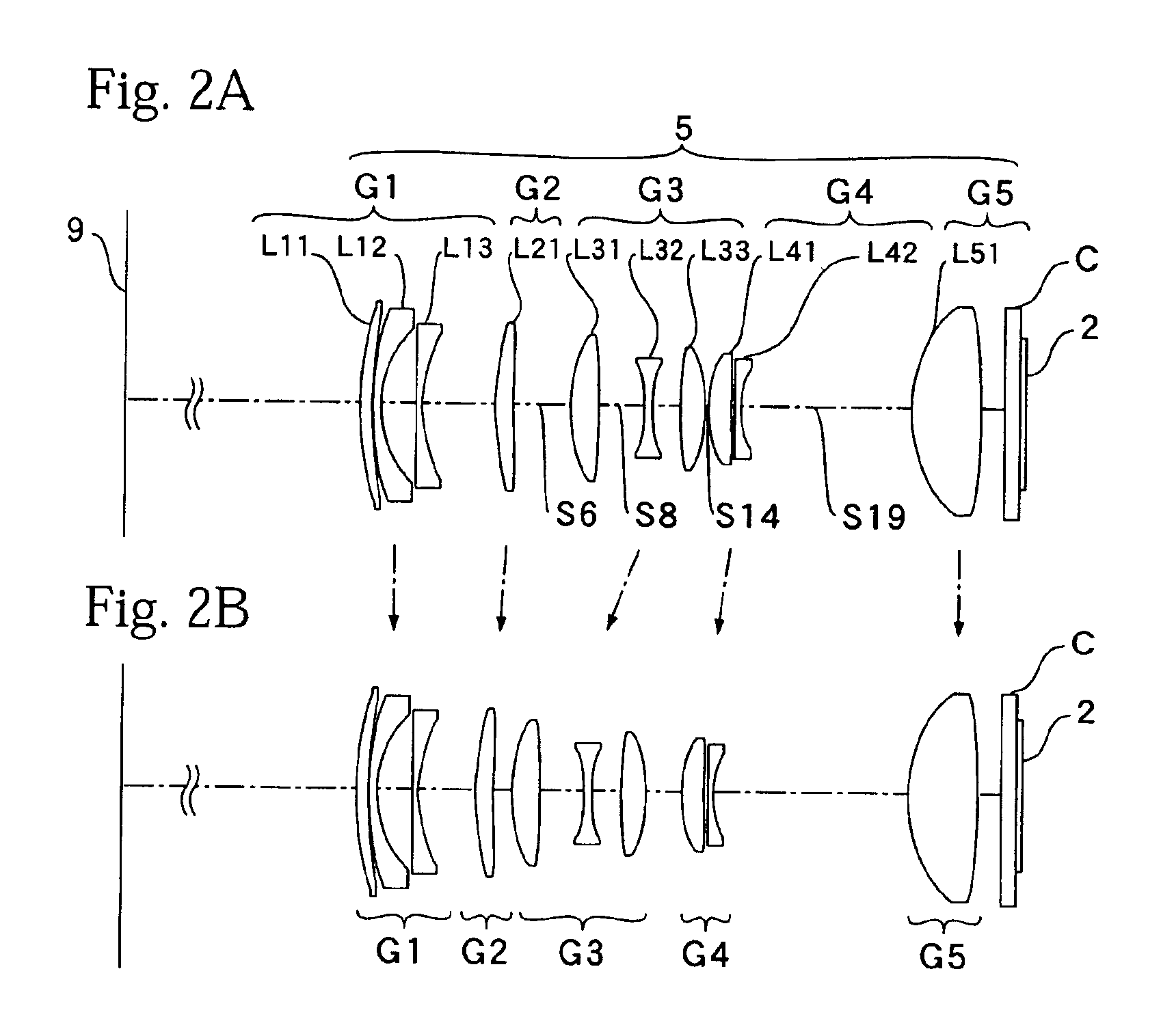
The lens arrangement of the projection lens system 5 according to the present invention is shown in FIG. 2 at the wide-angle end (FIG. 2A) and at the telephoto end (FIG. 2B). In the projection lens system 5 of the present embodiment, the lenses are grouped into the five lens groups G1, G2, G3, G4, and G5 on this order from the screen 9 side as described above and are composed of a total of ten lenses numbered L11 to L51. Detailed data on the respective lenses is given later in this specification.

The first lens group G1 on the screen side has an overall negative refractive power and is composed of a positive meniscus lens L11 that is positioned closest to the screen (i.e., at the front) and is convex on the screen side, a negative meniscus lens L12 that is convex on the screen side, and another negative meniscus lens L13 that is convex on the screen side, such lenses being aligned in this order. Also, out of these lenses, both surfaces (the third surface and the fourth surface) of th...

second embodiment

FIGS. 7A and 7B show another embodiment of a projection zoom lens system according to the present invention. The lens system 5 of the present embodiment is also composed of five groups using ten lenses numbered L11 to L51. The refractive powers of the respective lens groups G1 to G5 are the same as the zoom lens described above, and the types of the individual lenses that compose these lens groups G1 to G5 are the same as the lens system described above, apart from the lens L13 of the first lens group G1 that is a double-convex positive lens, the lens L41 of the fourth lens group G4 that is also a double-convex positive lens, and the lens L42 of the fourth lens group G4 that is a double-concave negative lens.

The lens data of the present embodiment is as shown below. It should be noted that in the following embodiment, the various reference codes are the same as in the first embodiment described above, so that description of such has been omitted.

Lens Data (No.2)

No.risinivi168.0983.1...


PUM


Abstract

A projection zoom lens system that is suited to a projector with a DMD is provided. The zoom lens system includes a fixed fifth lens group that is positioned on the light modulator side and is used as the field lens that transmits the illuminating light and the projection light and a first lens group for focusing that is fixed during zooming, and is constructed of five groups arranged in negative, positive, positive, negative, positive order from the screen side. The third lens group moves significantly during zooming as a variator, the second and fourth lens groups travel only so small distances as compensators but can correct various aberrations so well. Therefore, the movement of the fourth lens group that is the entrance pupil for the projection light outputted from the light valve is small, so that the active projection light is efficiently taken in and a projection zoom lens system that can project bright, clear images can be provided.

Description

BACKGROUND OF THE INVENTION1. Technical FieldThe present invention relates to a projection zoom lens system of a projector apparatus that enlarges and projects an image using a light valve, onto a screen.2. Description of the Related ArtConventionally, a liquid crystal panel is often used as the light valve of a projector. In recent years, in place of a liquid crystal panel, apparatuses equipped with a plurality of elements and forms an image by mechanically changing the direction of reflection of light using a micromachining technique have been realized. One example of such an apparatus is a DMD (digital mirror device or display) in which minute mirror-surface elements (micromirrors) are arranged in an array corresponding to pixels and image is formed by controlling the angles of the respective mirror surfaces. Compared to a liquid crystal panel, a light modulator (light valve) in which pixels are composed of micromirrors has faster response and produces a brighter image, so that s...

Claims


Application Information

Patent Timeline
Patent Type & Authority Patents(United States)
IPC IPC(8): H04N5/74G02B15/20G02B13/18G03B21/00G03B21/14
CPCG02B15/177H04N9/3141H04N5/7458G02B15/145523
Inventor YOSHIDA, MASASHI
Owner NITTO OPTICAL CO LTD
Why Eureka
Try Eureka