Cardiac vein lead and guide catheter

a catheter and lead technology, applied in the field of implantable medical device catheters and implantable medical device leads, can solve the problems of increasing the risk of infection, increasing the risk of damaging the lead or a blood vessel, and requiring considerable skill, so as to reduce the overall catheter size, reduce the number of tools and steps, and reduce the associated cost and procedural time

Inactive Publication Date: 2005-03-22
MEDTRONIC INC
View PDF15 Cites 131 Cited by
  • Summary
  • Abstract
  • Description
  • Claims
  • Application Information

AI Technical Summary

Benefits of technology

The present invention addresses these needs by providing a guide catheter that is easily steered through a vascular pathway for implantation of a medical lead without the use of an additional guidewire or stylet. By eliminating the need for a guidewire or stylet, the overall lead and guide catheter size can be reduced. Moreover, the present invention allows the guide catheter to be dynamically steered without incorporating additional components such as a pull wire in the guide catheter.
The present invention is realized by providing a guide catheter having a flexible distal segment and a medical lead having a high tensile strength and distal engaging member designed to interface with the distal catheter end such that the lead may be used in place of a pull wire for steering the guide catheter. The guide catheter includes a tubular body with a proximal handle and a flexible distal segment. The lumen of the catheter body is sized to allow easy passage of the medical lead. The distal segment, which may be tapered, is sized to form a slip fit with the distal end of the medical lead. The medical lead is fed into the guide catheter by inserting the proximal end of the lead into the distal end of the catheter and advancing the lead until the proximal lead end exits the proximal end of the catheter. The distal engaging member, which may be an electrode, is provided with a proximally facing, lateral surface that interacts with the distal end of the guide catheter to prevent the engaging member from entering the guide catheter.
The medical lead is characterized by a lead body having a high tensile strength such that traction applied to the proximal lead end is transferred in a substantially linear way to the distal engaging member. The lead body is preferably reinforced by a strengthening member, such as a polyester fiber, extending through the lead body lumen. The interaction of the lateral surface of the engaging member with the distal end of the guide catheter causes flexion of the distal, flexible catheter segment when traction is applied to the proximal lead end. This flexion results in a dynamic curvature of the distal catheter segment of varying radii, which variations are controlled by the amount of traction applied to the proximal lead end. The dynamic curvature of the distal segment allows the catheter to be precisely maneuvered through a range of geometries encountered in a vascular pathway.
The system provided by the present invention reduces the number of tools and steps required to guide a lead to an implant site, which, in turn, is expected to reduce the associated costs and procedural time for implanting a cardiac vein lead. Aspects of the present invention reduce the components required in a steerable guide catheter system allowing the overall catheter size to be reduced. The medical lead size may also be reduced since a guidewire or stylet is not needed, allowing the lead to be advanced deep into the cardiac veins for left heart sensing and / or stimulation.

Problems solved by technology

Repeated withdrawal and reinsertion of a stylet or guidewire, however, can be time consuming, increase the risk of infection, and increase the risk of damaging the lead or a blood vessel.
This procedure involves the use of several different instruments, requires considerable skill, and is generally time-consuming.

Method used


Image

  • Cardiac vein lead and guide catheter
  • Cardiac vein lead and guide catheter
  • Cardiac vein lead and guide catheter

Examples


Embodiment Construction

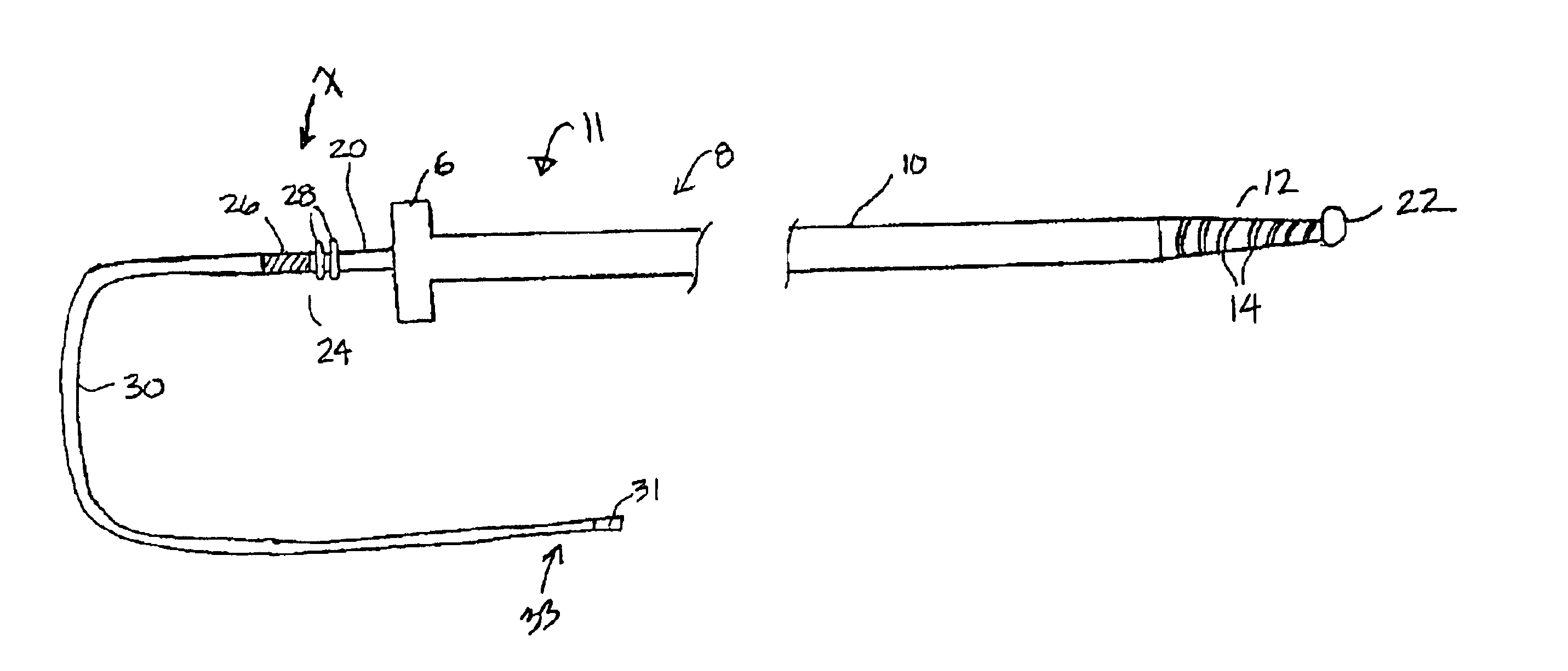
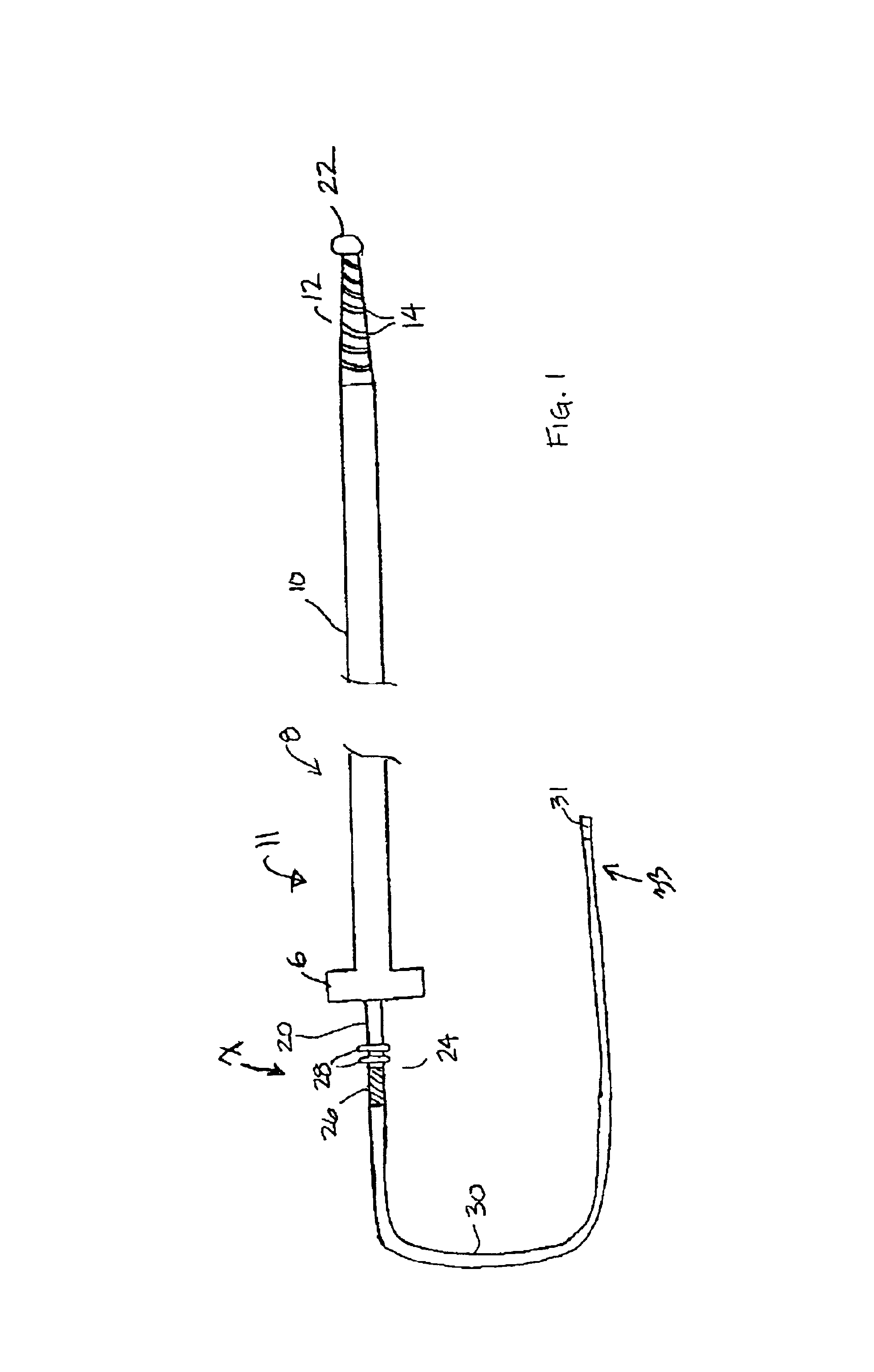
FIG. 1 is a plan view of a guide catheter and transvenous medical lead system in accordance with the present invention. As illustrated in FIG. 1, a guide catheter 8 according to the present invention includes a generally tubular catheter body 10 that is preferably formed from a biocompatible polymer such as polyurethane, a fluoropolymer, silicone rubber or other plastic acceptable for medical use. The catheter body 10 may optionally be reinforced with an embedded braiding or other reinforcing structure to provide stiffness to body 10 to allow advancement of catheter body 10 through a venous pathway. Catheter body 10, however, should also be flexible enough to adapt to a tortuous pathway. In one embodiment, catheter body 10 is preferably sized to allow passage through the coronary sinus to allow placement of a lead deep in the cardiac veins for left heart stimulation and / or sensing. As such, catheter body 10 preferably has an outer diameter on the order of approximately 4 to 5 French...


PUM


Abstract

A guide catheter and medical lead are provided wherein the lead may be used as a pull wire to steer the guide catheter. The guide catheter is provided with a flexible distal segment and the lead is provided with a distal engaging member, which may also serve as an electrode. The distal engaging member interacts with the distal catheter end such that traction applied to the proximal lead end causes flexion of the distal segment of the catheter to advance the flexible distal segment between a non-flexed position and a flexed position, allowing the catheter to be steered around obstacles.

Description

FIELD OF THE INVENTIONThe present invention generally relates to implantable medical device catheters and implantable medical device leads, and more particularly, the present invention relates to a guide catheter for use in implanting a medical lead wherein the guide catheter may be steered to a desired location in a patient's body using a high tensile strength medical lead as a pull wire.BACKGROUND OF THE INVENTIONTransvenous endocardial leads may be placed inside a chamber of a patient's heart by passing the lead through a venous entry site, such as the subclavian vein or the cephalic vein, or a tributary thereof, along a venous pathway into the superior vena cava and into the right cardiac chambers. Cardiac vein leads may be advanced further, from the right atrium through the coronary sinus ostium into the coronary sinus and ultimately into one of the various cardiac veins for stimulation and / or sensing of the left heart chambers.Cardiac lead placement is important in achieving p...

Claims


Application Information

Patent Timeline
Patent Type & Authority Patents(United States)
IPC IPC(8): A61N1/05
CPCA61N1/056A61N1/057A61N2001/0585A61N2001/0578
Inventor SOMMER, JOHN L.
Owner MEDTRONIC INC
Why Eureka
Try Eureka