Switching regulator for implantable spinal cord stimulation

a switching regulator and spinal cord technology, applied in electrotherapy, therapy, etc., can solve the problems of inability to meet the needs of small implantable medical devices, inefficient power use, and relatively slow charge pump circuits, so as to avoid saturation of the inductor core, efficient operation of the switching regulator, and high duty cycle

Inactive Publication Date: 2005-03-22
BOSTON SCI NEUROMODULATION CORP
View PDF15 Cites 158 Cited by
  • Summary
  • Abstract
  • Description
  • Claims
  • Application Information

AI Technical Summary

Benefits of technology

In accordance with another aspect of the invention, the switching regulator may operate in one of two duty cycles. When the switching regulator is turned on, or if the voltage of the holding capacitor drops below a threshold, a low duty cycle is selected. When the voltage of the holding capacitor exceeds the threshold, a higher duty cycle is selected. By matching the duty cycle to the

Problems solved by technology

Charge pump circuits with course voltage resolution (i.e., a small number of capacitors) result in inefficient power use because the current resulting from the excess voltage is dissipated.
Charge pump circuits with fine resolution require large numbers of capacitors, and are therefore not well suited for small implantable medical devices.
Moreover, charge pump cir

Method used


Image

  • Switching regulator for implantable spinal cord stimulation
  • Switching regulator for implantable spinal cord stimulation
  • Switching regulator for implantable spinal cord stimulation

Examples


Embodiment Construction

The following description is of the best mode presently contemplated for carrying out the invention. This description is not to be taken in a limiting sense, but is made merely for the purpose of describing the general principles of the invention. The scope of the invention should be determined with reference to the claims.

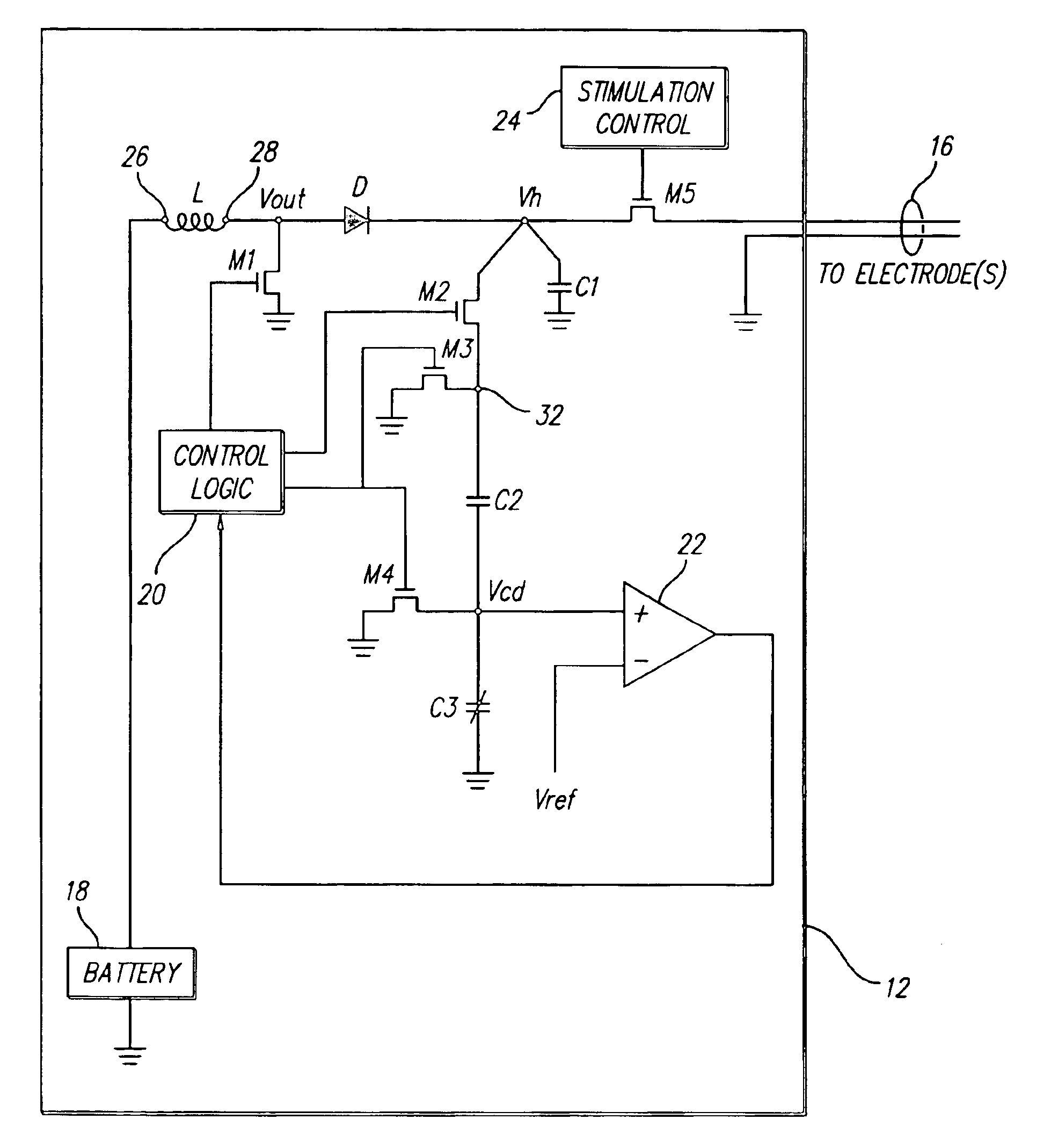
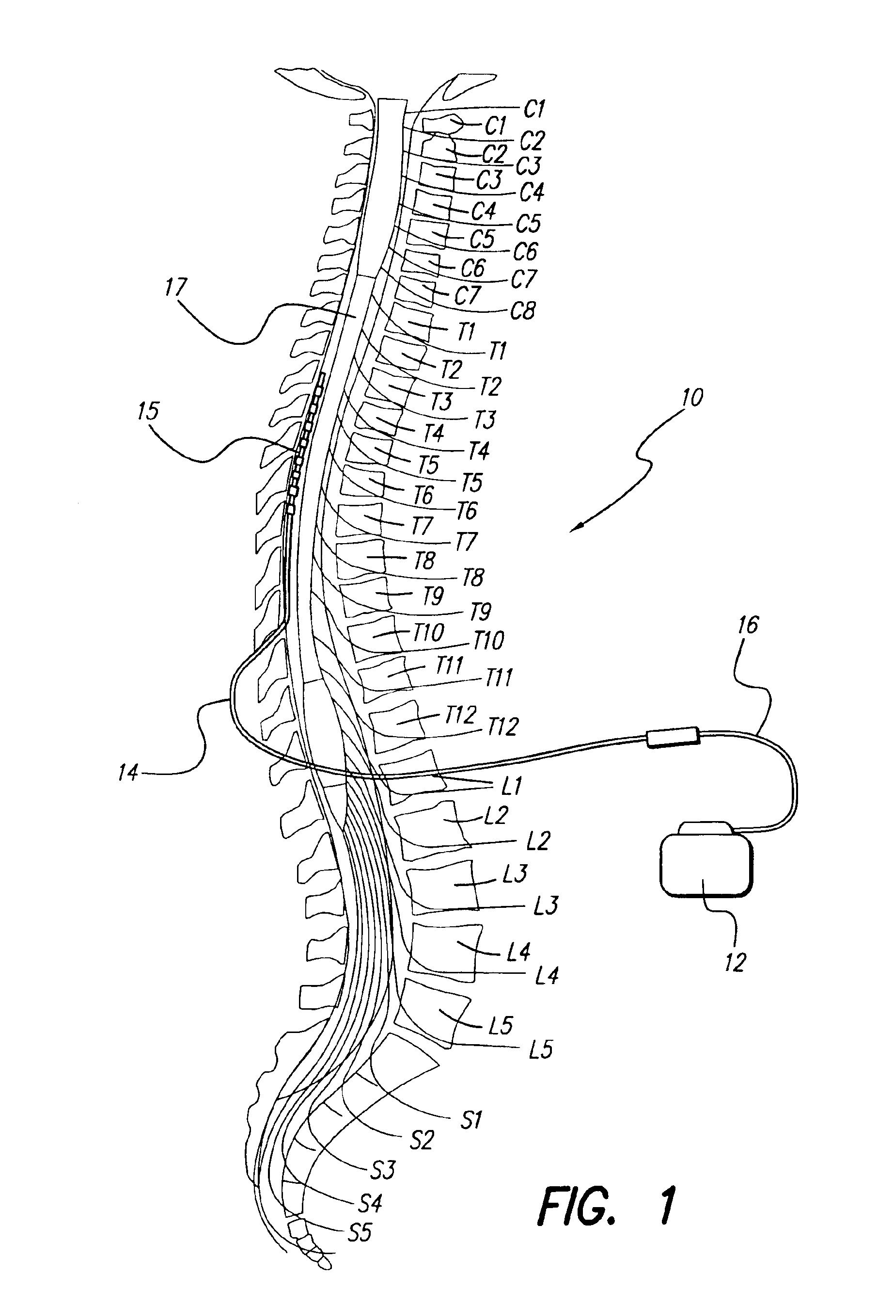
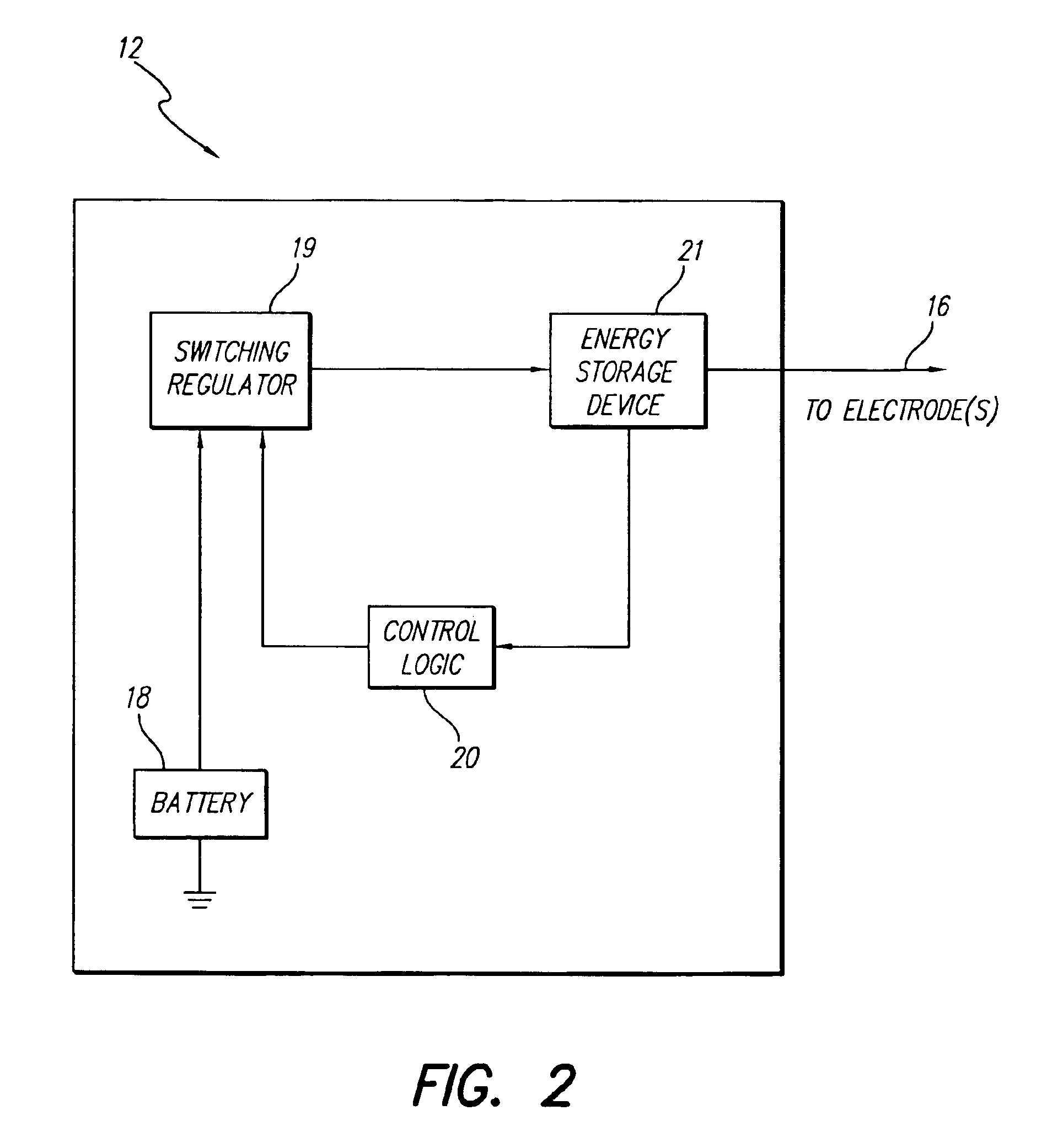
The improved switching regulator of the present invention efficiently provides an implantable device with a multiplicty of voltage levels for tissue stimulation or other uses. A representative implantable Spinal Cord Stimulation (SCS) system 10 that would benefit from the present invention is shown in FIG. 1. The SCS system 10 comprises an Implantable Pulse Generator (IPG) 12 electrically connected by an electrode lead extension 16 to a proximal end of an electrode lead 14. An electrode array 15, residing on a distal end of the electrode lead 14, is implanted along spinal cord 17 of a patient. The IPG 12 provides stimulation current that is conducted by the electr...


PUM


Abstract

An improved switching regulator for implantable medical devices includes a control circuit with a capacitor divider to conserve energy, and selectable duty cycles to efficiently match the duty cycle to the charge level in a holding capacitor. The switching regulator charges the holding capacitor to commanded voltage levels, and the holding capacitor provides current for tissue stimulation. The commanded voltage level is reached by “pumping-up” the holding capacitor with the output of the switching regulator. For control purposes, the high voltage (i.e., the voltage across the holding capacitor) is divided between a fixed capacitor and a variable capacitor, and the voltage between the fixed capacitor and the variable capacitor (i.e., the divided voltage) is compared to a reference voltage. The result of the comparison is used to turn-off the switching regulator once the commanded voltage level is reached. The switching duty cycle is set to one of two values. At start-up, or when the output voltage drops below a determined threshold, a low duty cycle is used. Once the output voltage reaches the threshold, a higher duty cycle is used.

Description

BACKGROUND OF THE INVENTIONThe present invention relates to implantable medical devices, and more particularly to a voltage converter, for use within an implantable Spinal Cord Stimulation (SCS) system, or similar implantable device, that uses a switching regulator to provide a voltage step-up function.Many implantable medical devices, such as neural stimulators, sensors, and the like, utilize a battery as a primary source of operating power. Other types of implantable devices, such as known cochlear stimulators, rely on transcutaneous inductive power transmission from an external device to the implantable device, where an induced voltage is thereafter rectified and filtered in order to provide the primary operating power for the implantable device. In both types of devices, a battery-powered device or an RF-powered device, there: is a frequent need to derive other operating voltages within the device from the primary power source. That is, there is a frequent need to step up the vo...

Claims


Application Information

Patent Timeline
IPC IPC(8): A61N1/32A61N1/34A61N1/08
CPCA61N1/08A61N1/36125A61N1/36071
Inventor HE, YUPINGPETERSON, DAVID K. L.
Owner BOSTON SCI NEUROMODULATION CORP
Why Eureka
Try Eureka