
Techniques for spreading zeros in a digital filter with minimal use of registers

Inactive Publication Date: 2005-03-22
CIRRUS LOGIC INC
View PDF6 Cites 13 Cited by
  • Summary
  • Abstract
  • Description
  • Claims
  • Application Information

AI Technical Summary

Benefits of technology

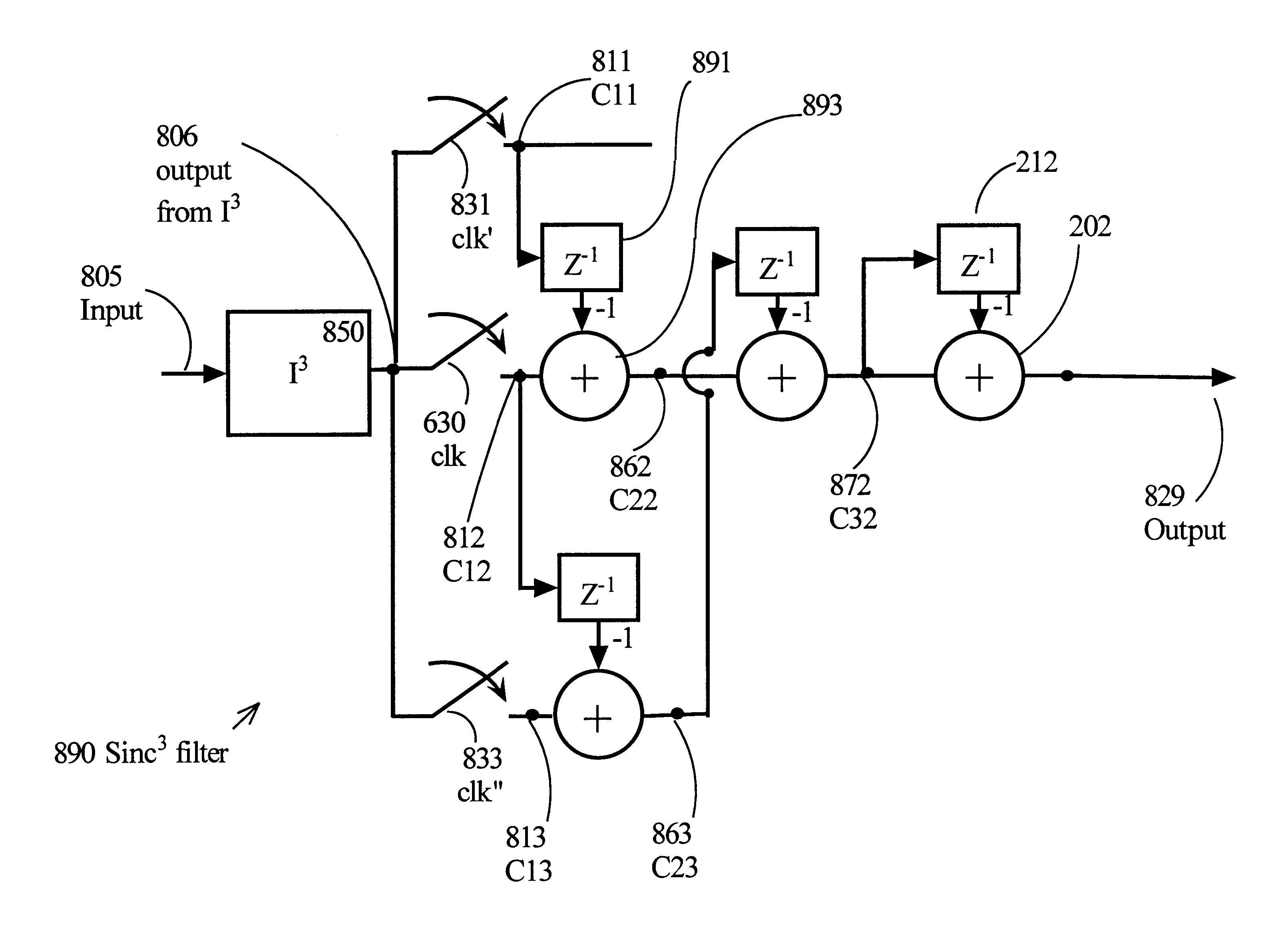
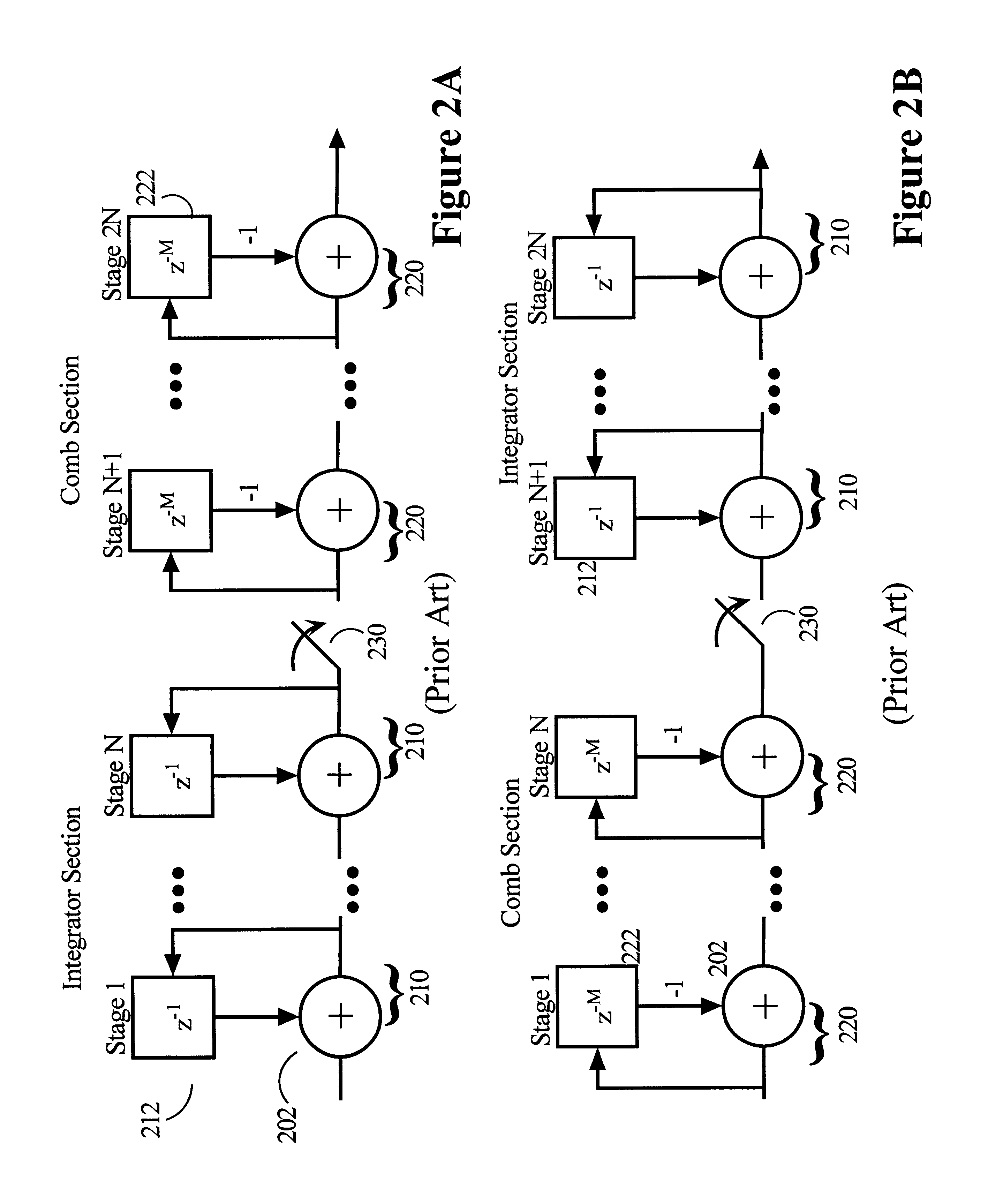
A new architecture for implementing SincN filters is introduced, based on the Hogenauer architecture, which permits arbitrary zero placement. Zero splitting is achieved by observing the data dependencies in the comb section of a baseline filter, and subsequently translating them into a new architecture that can be implemented in hardware with a small cost in chip size or implemented in software in a digital signal processor with small cost in computation. The architecture retains the inherent flexibility and conceptual simplicity of the Hogenauer SincN architecture. Since zero splitting generally requires additional sampling of integrator section output, the filter is usually somewhat larger than the corresponding Hogenauer filters without split zeros.
An advantage of the filters of the present invention is a considerable increase in the design options available to the filter designers. Splitting the zeros may also be used to reduce the noise that gets aliased back into the passband. Splitting the zeros also allows selective simultaneous attenuation of power line frequencies, such as 50 Hz and 60 Hz. Because of the large power associated with these line frequencies, they often cause introduction of “noise” into electronic equipment. Placing filter zeros at one or more of these frequencies can significantly reduce noise of the unwanted line frequency and increase the SNR of a device. Simultaneous rejection of both 50 Hz and 60 Hz by the same filter is desirable so that the same filter can be used in different regions of the world without changes. Similarly simultaneous attenuation of other frequencies is possible.

Problems solved by technology

Because of the large power associated with these line frequencies, they often cause introduction of “noise” into electronic equipment.

Method used


Image

  • Techniques for spreading zeros in a digital filter with minimal use of registers
  • Techniques for spreading zeros in a digital filter with minimal use of registers
  • Techniques for spreading zeros in a digital filter with minimal use of registers

Examples


example 1

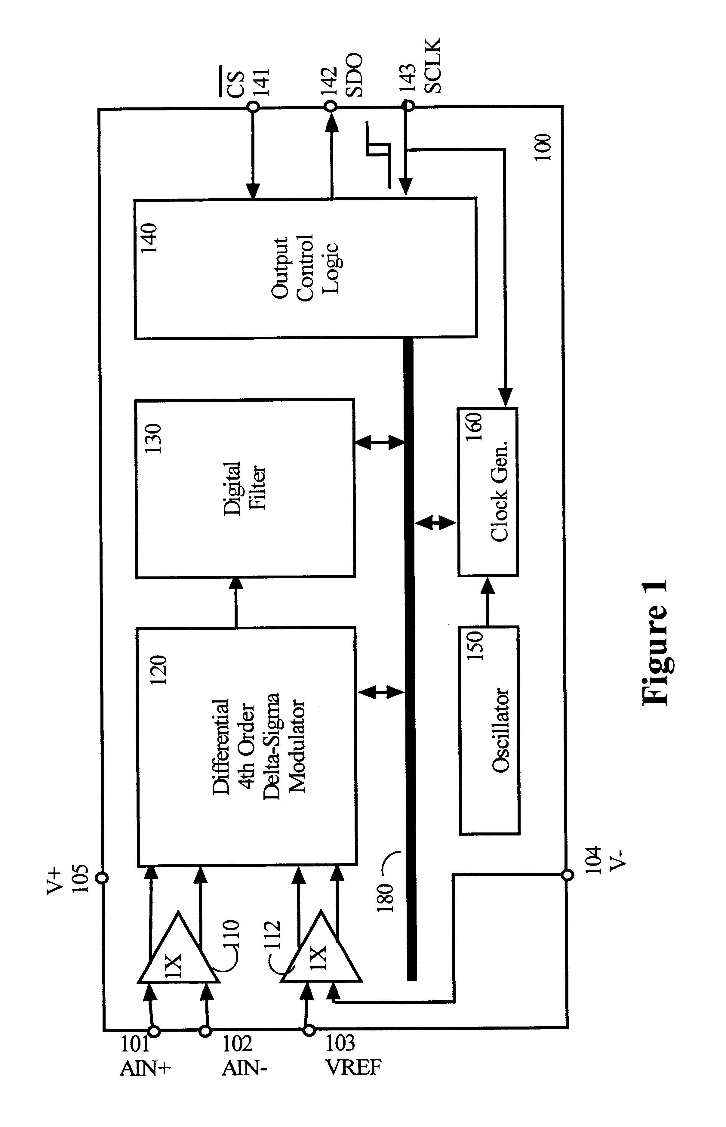
The first example designs a new Sinc3 filter where R is 16 and the split frequencies correspond to a sampling of 18 cycles and 14 cycles. For example, where fS is 8192 Hz, as in the sample ADC chip 100, an R of 16 yields an fSS of 512 Hz. The 18 cycles sampling corresponds to a frequency of about 455 Hz, (a frequency offset of −57 Hz and a time delay of two more time units), and 14 cycles sampling corresponds to a frequency of about 585 Hz (a frequency offset of +73 Hz and a delay of two fewer time units). The delays are symmetrically distributed around R, but the frequencies are not exactly symmetric. In the time domain, measured in number of sampling cycles, fSS corresponds to the integer factor fS / R. In other embodiments the delays need not be symmetrically distributed around R. But asymmetric distribution of delays generally leads to more complex traces and usually requires that more samples be retained.

FIGS. 6B and 6C correspond generally to FIGS. 5A and 5B, discussed above, re...

example 2

As another example of the method and resulting apparatus, aSinc4 filter is designed with simultaneous rejection of 50 Hz and 60 Hz line frequencies. A data dependency graph was developed for a baseline Sinc4 filter having two zeros at one frequency (such as 50 Hz) and two zeros at another frequency (such as 60 Hz). By assuming fS is about 870 Hz and fSS is about 54 Hz, R is 16. If two roots are placed at a frequency corresponding to a time interval of 16+2 and two roots are placed symmetrically at a frequency corresponding to a time interval of 16−2, then the roots actually occur at frequencies of about 48 Hz and 62 Hz, respectively. (This simple example was chosen to keep the R manageably small to serve as an illustration. At a higher sampling frequency, fS, and a higher value for R, such as the sample ADC chip 100 which has an fS value of 8192 Hz and an R of 153, roots can be placed closer to 50 and 60 Hz than in the simple example. Example 3 describes the case of the sample ADC.)...

example 3

A data dependency graph was generated for another baseline circuit (not shown) which is a Sinc4 filter having four separate zeros with time delays symmetrically distributed around fSS. The zeros for this example were fSS−β′, fSS−α′, fSS+α and fSS+β, corresponding to time delays of b, a, −a and −b, respectively. In this example, fS is 8192 Hz. To achieve at least 80 dB attenuation from 47 to 63 Hz, R was 153 (for an OWR of 53.54 Hz), a was 9 cycles and b was 20 cycles. This places zeros at 47.35 Hz, 50.57 Hz, 56.89 Hz, and 61.59 Hz, much closer to the line frequencies of 50 and 60 Hz than previous examples. The resulting filter circuit 1100 is shown FIG. 11.

Referring to FIG. 11, it can be seen that nine decimators, 1181 to 1189, are needed to sample the input 1105 from the I4 integrators 1150. Note that each decimator is connected in series to four adders or fewer. Signals from another decimator are, in some instances, incorporated by connections with a single delay register 212 asso...


PUM


Abstract

Techniques related to a digital filter include at least one decimator disposed between an integrator section and a comb section such that the transfer function of the filter has split zeros. The resulting filter implementation employs considerable less silicon real estate than other prior art implementations with spread zeros, and has more design flexibility with improved resulting performance than the Hogenauer implementation.

Description

FIELD OF THE INVENTIONThe invention relates to digital filters, and more particularly to flexibly positioning N zeros of a digital SincN filter with a minimal use of extra registers.BACKGROUND OF THE INVENTIONTechniques for sampling an analog signal, converting the sampled signal to digital and processing that signal using digital techniques are known in the art. An example of an analog signal source is that provided by a measurement sensor, such as a thermocouple. The sampled analog signal is converted to digital. Conversion to digital may produce a digital stream of one or more bits. Typically, the analog signal is sampled at one rate, the sampling frequency (fS), while the digital output is needed at a different rate, the output word rate (OWR).Filters for doing such processing, such as finite impulse response (FIR) filters and FIR Sinc filters, are known. Digital filters such as Sinc filters can be implemented using digital circuits for performing a variety of mathematical opera...

Claims


Application Information

Patent Timeline
IPC IPC(8): G06F17/17H03H17/02H03H17/06
CPCH03H17/0671H03H17/0251H03H2017/0678
Inventor NANDA, KARTIKKASHA, DAN
Owner CIRRUS LOGIC INC
Learn More