
Combined waveform and data entry apparatus and method for facilitating fast behavioral verification of digital hardware designs

Inactive Publication Date: 2005-03-22
XILINX INC
View PDF20 Cites 85 Cited by
  • Summary
  • Abstract
  • Description
  • Claims
  • Application Information

AI Technical Summary

Benefits of technology

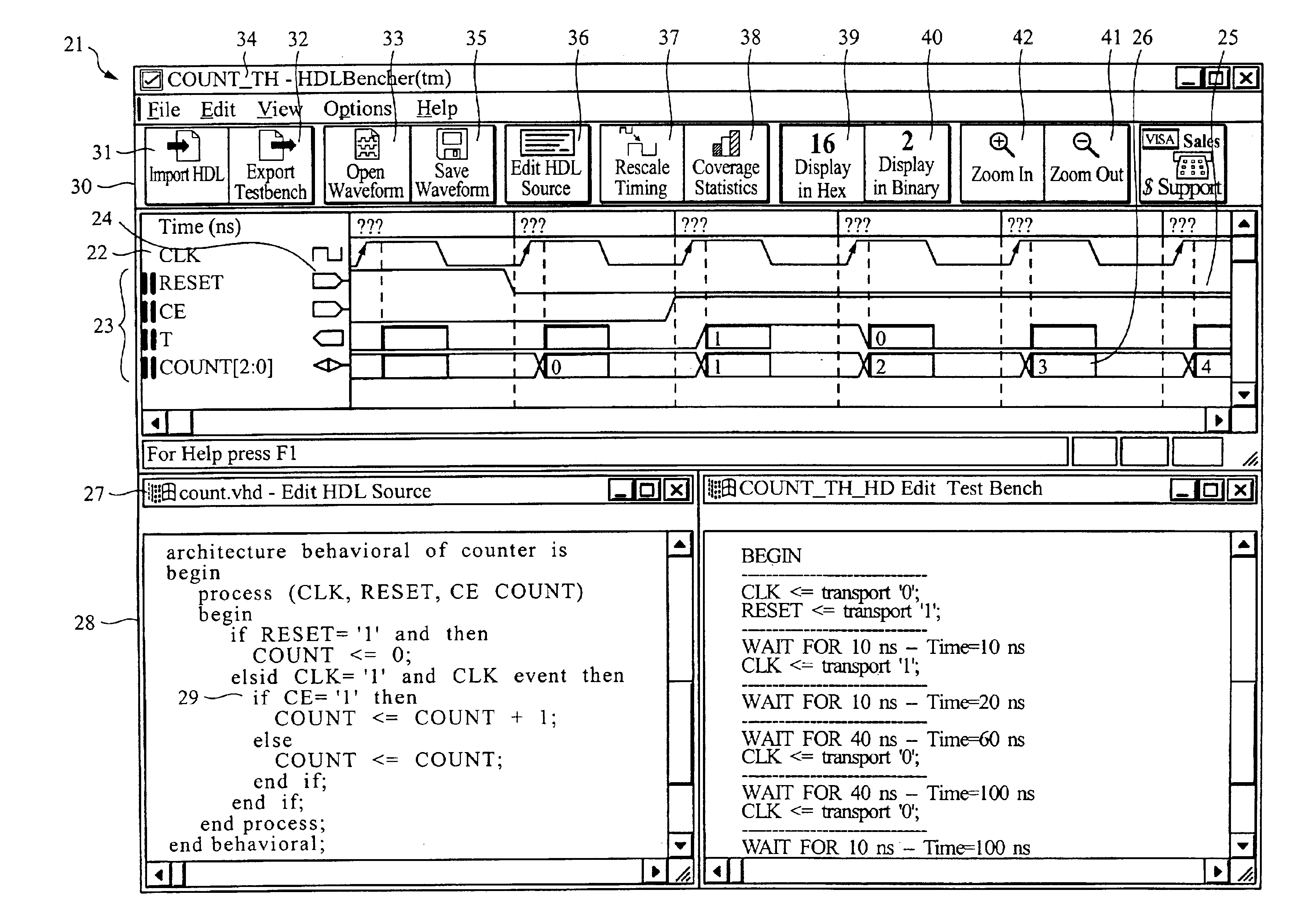
The present invention utilizes a unique combined waveform-and table data entry system to facilitate fast behavioral verification of digital hardware circuit designs. A cell based, tabular data entry system consists of rows of signal names and columns of cell values containing time-varying data, which are displayed as waveforms.
The HDL Editor and the wavetable Editor contain two-way links, which allows them to maintain consistency and coherency between the test pattern under development and the input / output interface of the UUT.

Problems solved by technology

If signal waveforms are not properly synchronized, the electrical circuit may not behave as intended, and consequently generate unwanted operational errors.
However, because table-based descriptions of data lacks visual content, it is inherently ill suited to convey the logical relationship among the same data.
A problem with simulators is that they cannot be used until the behavioral description of the design has been properly and manually encoded as a script or as an HDL test bench description.
This in itself is an error-prone and tedious process.
Likewise, HDL test bench descriptions of test pattern data are, by themselves, static, thereby requiring considerable effort to modify in response to changes in the underlying electrical circuit specification.
Another problem with traditional simulators is that, once a problem is encountered, the test pattern must be modified manually in order to keep it up to date.
Were this not the case, any HDL test bench description generated from the test pattern would no longer correctly reflect the user's intent.
The order of signals in the port is changed, thereby causing test benches which rely on port order for instantiation to be incompatible.
While these solutions reduce the occurrences of port map problems, they do not eliminate them.

Method used


Image

  • Combined waveform and data entry apparatus and method for facilitating fast behavioral verification of digital hardware designs
  • Combined waveform and data entry apparatus and method for facilitating fast behavioral verification of digital hardware designs
  • Combined waveform and data entry apparatus and method for facilitating fast behavioral verification of digital hardware designs

Examples


Embodiment Construction

In the following description of the preferred embodiment, reference is made to the accompanying drawings that form a part thereof, and in which is shown by way of a illustration a specific embodiment in which the invention may be practiced. It is to be understood that other embodiments may be utilized and structural changes may be made without departing from the scope of the present invention.

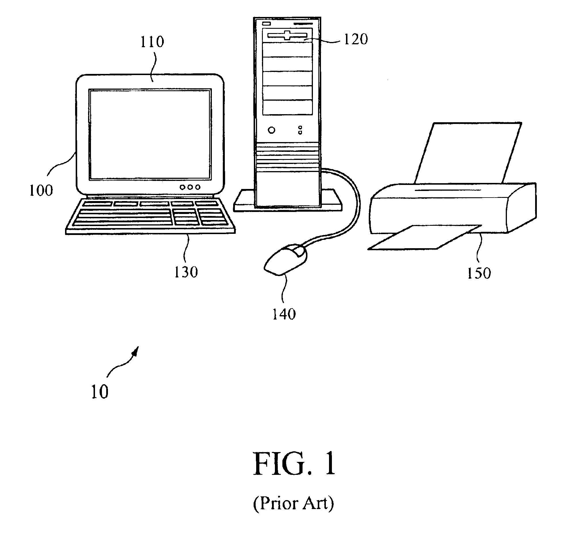
Referring first to FIG. 1, a combined waveform and data entry system for facilitating fast behavioral verification of digital hardware designs is designated generally by the number 10 and comprises a personal computer (PC) 100 including a monitor 110, a disk storage device 120, input devices such as a keyboard 130 and a mouse 140 and printer peripherals 150. The preferred embodiment of the present invention runs under Microsoft Windows operating systems.

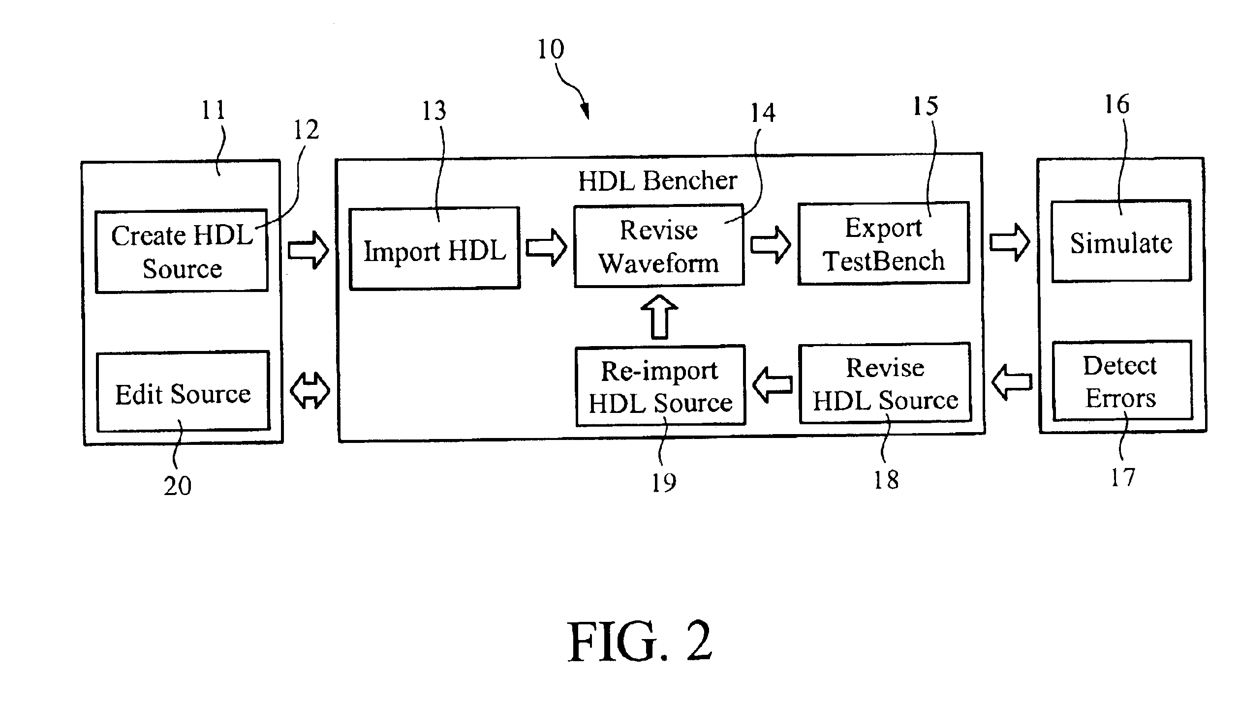
FIG. 2 shows the process flow used for developing test benches for arbitrary VHDL and VERILOG® designs utilizing the present invention.

The Text...


PUM


Abstract

A computer implemented apparatus and method that automates the entry, modification, analysis, and generation of test benches from electrical circuits, both of which are specified as hardware description language (HDL) files. The computer implemented-method and apparatus also provides a unique mechanism that blends entry and display of timing requirements that must be met by the electric circuit.

Description

BACKGROUND OF THE INVENTION1. Field of the InventionThe invention relates to an electrical circuit timing and verification system, and particularly to a computer-based system that automates and facilitates the entry, modification, analysis and generation of test benches in multiple HDL digital hardware designs via a unique wavetable spreadsheet interface which simultaneously displays data as both waveforms and numerical cell values.2. Description of Related ArtHardware Description Languages (HDLs) are language specifications for precisely describing the behavior and programming the function of electrical circuits. Test benches are HDL descriptions specialized in describing and verifying the behavior of electrical circuits.Events and data in electrical circuits are routinely described by signals (one bit wide), and vectors (two or more bits wide). The manner in which signals and vectors change as time flows are described by displaying signal snapshots sequentially. The resulting obje...

Claims


Application Information

Patent Timeline
IPC IPC(8): G06F17/50
CPCG06F17/5022G06F30/33
Inventor BLOOM, ANDREW MAURICEESCOTO, RODRIGO JOSE
Owner XILINX INC
Learn More