Vessel for enabling a uniform gravity driven flow of particulate bulk material therethrough, and direct reduction reactor incorporating same

a gravity-driven flow and particulate bulk material technology, which is applied in the direction of liquid transfer devices, liquid handling, transportation and packaging, etc., can solve the problems of difficult cost-effective incorporation, entail additional operational costs, and inability to practice fluid injection in many applications, etc., and achieves the effect of promoting a uniform flow of particulate bulk materials and being easy to manufactur

Inactive Publication Date: 2005-03-29
HYSLA S A DE
View PDF8 Cites 35 Cited by
  • Summary
  • Abstract
  • Description
  • Claims
  • Application Information

AI Technical Summary

Benefits of technology

In view of this prior art, it is an object of the invention to provide a vessel or container that is inexpensive to manufacture and that promotes a uniform flow of particulate bulk materials therethrough. In particular, the stoppages caused by said materials hanging or dome bridging inside the converging zone of such container is to be minimized without resorting to moving parts.

Problems solved by technology

The measures proposed by this patent however, although effective in achieving its object, are difficult to incorporate in a cost-effective manner because the construction of the helical step along the conical portion of the container raises the costs incurred by the actual cutting and conformation of the metal sheet employed for constructing such container.
The injection of a fluid may not be possible to practice in many applications and entails additional operational costs.
The concept described in this patent however does not eliminate the formation of domes by the solid particles.
The bin of this patent also has the disadvantage of a complicated and costly construction because of the shape of the segments as shown in the patent.

Method used


Image

  • Vessel for enabling a uniform gravity driven flow of particulate bulk material therethrough, and direct reduction reactor incorporating same
  • Vessel for enabling a uniform gravity driven flow of particulate bulk material therethrough, and direct reduction reactor incorporating same
  • Vessel for enabling a uniform gravity driven flow of particulate bulk material therethrough, and direct reduction reactor incorporating same

Examples


Embodiment Construction

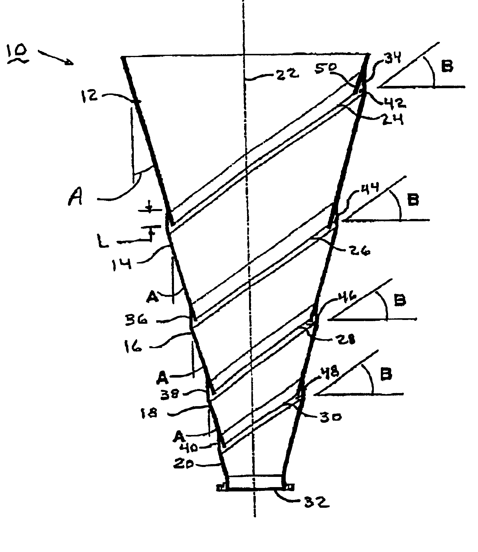
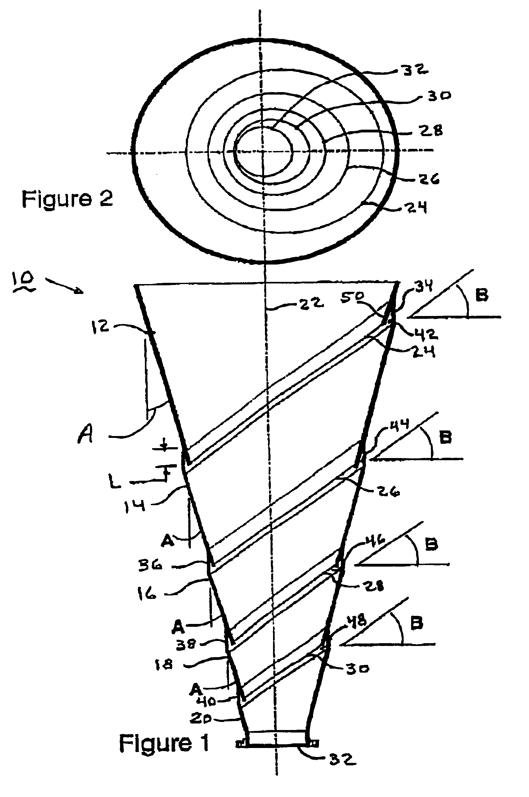
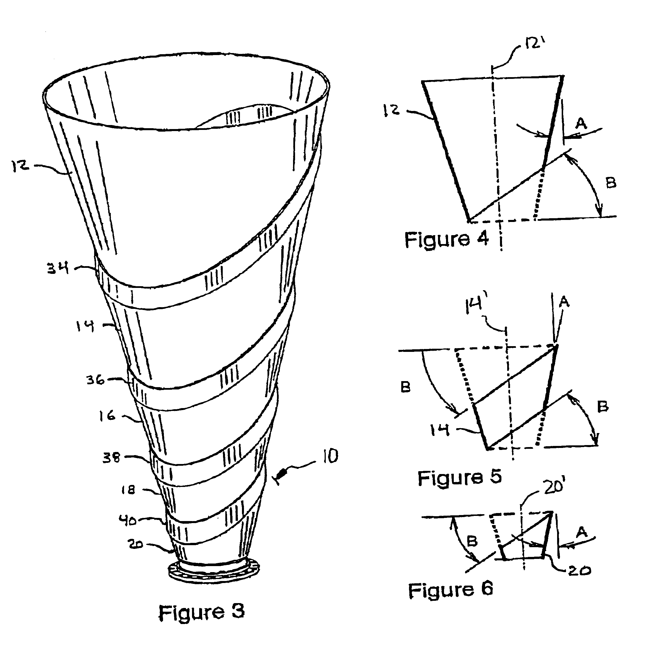
In the figures, a preferred embodiment of the present invention is depicted, and the inventive vessel is generally designated with reference numeral 10. Throughout the drawing figures, the same or corresponding element are designated with identical reference numerals.

Although vessel 10 in FIG. 1 is depicted as having various conical segments 12, 14, 16, 18 and 20, it would be sufficient to embody the present invention, if the vessel 10 only comprised an upper wall segment 12, a lower wall segment 14, and an intermediate wall segment 34. In FIG. 1, various of these upper wall segments, lower wall segments and intermediate wall segments are depicted, the intermediate wall segments linking the respective upper and lower wall segments. In this manner, for example, conical wall segment 18 in FIG. 1 functions as an upper wall segment for the combination of wall segments 18, 40 and 20, and at the same time as a lower wall segment for the combination consisting of wall segments 16, 38 and 1...


PUM


Abstract

So as to provide a container that is inexpensive to manufacture and that promotes a uniform flow of particulate bulk materials therethrough, a vessel is suggested comprising at least two wall segments having a generally downwardly converging wall defining a vertical axis for the vessel, a first upper segment being vertically arranged above a second lower segment, each one of the wall segments having an upper edge and a lower edge, the perimeter of the upper edge of the second lower wall segment being larger than the perimeter of the lower edge of the first upper wall segment the lower edge of the first upper wall segment and the upper edge of the second lower wall segment being positioned proximate to each other and cooperating to provide an enlargement of the cross-sectional area of the volume occupied by the particulate solid material.

Description

FIELD OF THE INVENTIONThe invention relates to an improved configuration of bins, hoppers, silos, reactors, and more generally to any vessel for handling, processing, transporting or temporarily storing particulate bulk materials.A particularly useful application of the invention is related to a Direct Reduction Reactor of particulate iron ores.BACKGROUND OF THE INVENTIONIt is common in many industries to use containers or vessels for handling, processing, transporting or temporarily storing particulate bulk materials. The geometrical configuration of such containers or vessels is of utmost importance in order to assure the desired type of flow of particles through said vessels. Depending on such factors and characteristics of the particles, as for example, the size and shape of the particles, the friction forces developed in the body of the bulk material as well as the friction forces between the particles and the wall of the container and the pressure exerted on said particles cau...

Claims


Application Information

Patent Timeline
Patent Type & Authority Patents(United States)
IPC IPC(8): B65D88/00B65D88/28
CPCB65D88/28
Inventor QUINTERO-FLORES, RAUL GERARDOBECERRA-NOVOA, JORGE OCTAVIOCELADA-GONZALEZ, JUANGUERRA-REYES, MARIA TERESALOPEZ-GOMEZ, RONALD VICTOR MANUEL
Owner HYSLA S A DE
Why Eureka
Try Eureka