Metal stud building system and method

a technology of metal studs and building systems, applied in the direction of rod connections, manufacturing tools, mechanical equipment, etc., can solve the problems of cracks or distortions in the walls of the building in which they are used, little if any vertical displacement of the floor or roof, unsightly and unacceptable cracks in the wall coverings,

Inactive Publication Date: 2005-03-29
STOVER DONIE
View PDF7 Cites 130 Cited by
  • Summary
  • Abstract
  • Description
  • Claims
  • Application Information

AI Technical Summary

Benefits of technology

It is an object of this invention to provide an improved stud assembly system and method for permitting relative vertical movement between the ceiling or roof of a structure and the stud.

Problems solved by technology

Such construction has resulted in substantial problems, in that little if any vertical displacement of the floor or roof, at the top of the studs, could be tolerated.
The fixed relationship of the non-load-bearing studs and the floors or roofs connected to the top ends of the studs results in longitudinal compressive stresses on the studs, which frequently causes the studs to buckle laterally at intermediate locations, creating cracks or distortions in the walls of the building in which they are used.
If the studs are rigidly secured at both the top and bottom, between the floor of the room and its ceiling, unsightly and unacceptable cracks occur in the wall covering.
In addition, the integral structure of the wall is weakened as a result of the buckling or partial buckling of the studs.
When the load is lessened (in the case of an office building, by all of the workers leaving at the end of a day, or in the case of a roof, by the melting of snow), the cracks in the walls increase as the walls expand in response to the lessening vertical pressure on the studs.
The studs themselves undergo a stretching or lengthening after their earlier buckling, which further contributes to the weakness of the wall.
If the clip were to be extended beyond these downwardly depending flanges, it would interfere with the attachment of drywall to the stud, since portions of the clip directly underlie the inwardly edges of the stud.
As with the Gilmour patent mentioned above, the system of DeFrancesco also does not provide any provision for drywall overlap; so that sound can travel over the top of a wall built with this system.
The system, however, does not allow for drywall butt joints.
This would defeat the purpose of the whole system.
In addition, the system of DeFrancesco, as well as the system of Gilmour, preclude the running of any conduit through the wide or inside portion of the studs, since the clips of both of these patents completely overlie this portion.
Consequently, no conduit could be run through the stud / clip assembly without securing the parts together.
As a consequence, the structures of both Gilmour and DeFrancesco clearly limit the location of any conduit running through the interior of the wall to a position substantially removed from the clip assembly itself.
The disclosure of the Becker patents, however, does not show any guide whatsoever to hold the studs against tipping or shifting within the header.
In the event of an earthquake, however, the studs are not held against lateral movement (particularly longitudinally of the header); so that the wall structure is subject to substantial damage in the event of an earthquake.
The structure disclosed in this patent, however, is not directed to slip fit interconnections between a head track and vertical studs to allow relative movements between the two.

Method used


Image

  • Metal stud building system and method
  • Metal stud building system and method
  • Metal stud building system and method

Examples


Embodiment Construction

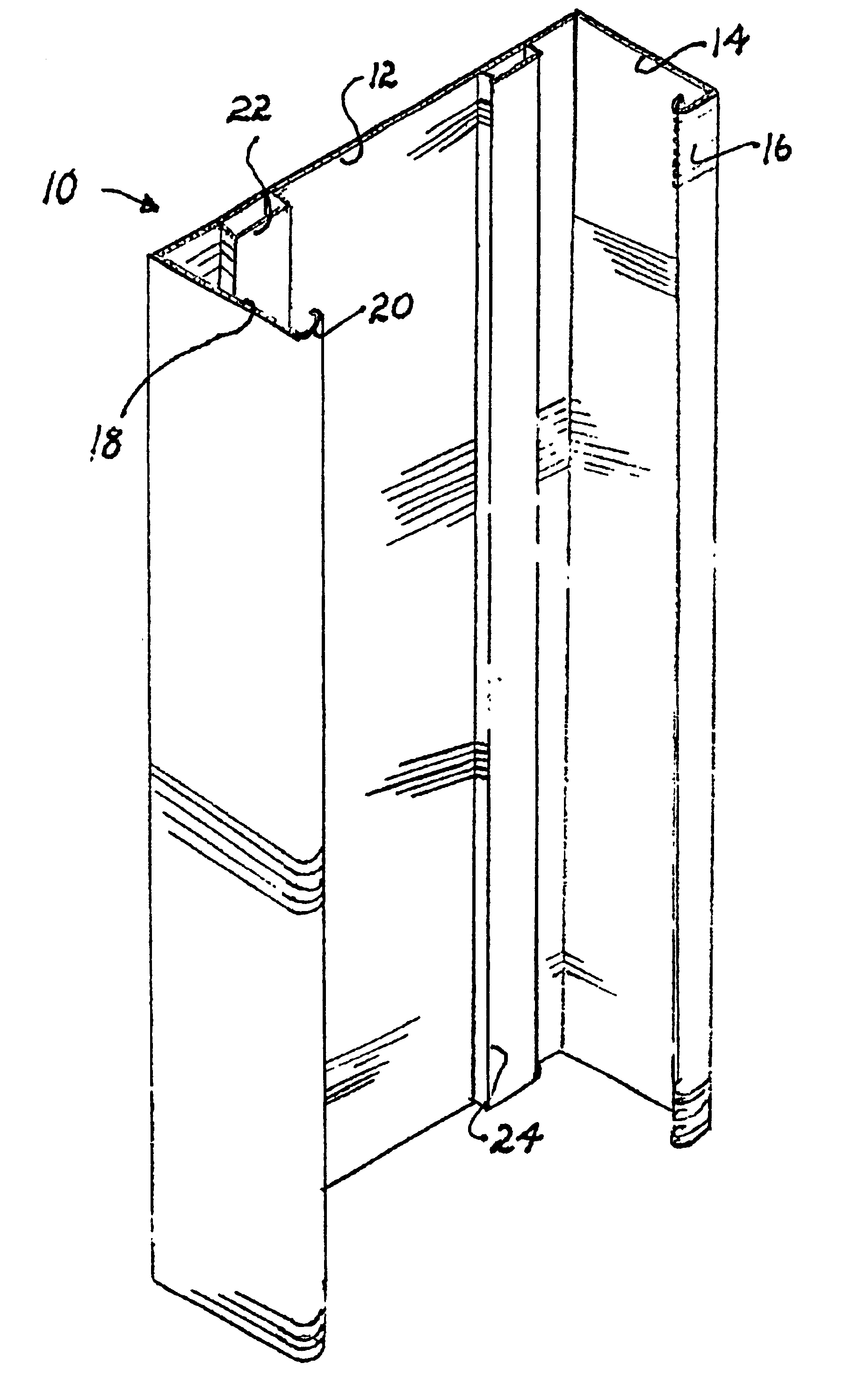
Reference now should be made to the drawings, in which the same or similar components are designated by the same reference numbers throughout the different figures. FIG. 1 is a front perspective view of a metal stud made of galvanized steel, extruded aluminum or other suitable material, which incorporates the features of a preferred embodiment of the invention.

The stud 10 and has a generally U-shaped cross section. The bight of the cross section is a main member 12, typically located on the interior of a wall in which the stud 10 is used. The longitudinal edges of the member 12 have attached to them a pair of side members 14 and 18. The side members 14 and 18 may be integrally formed with the main member 12, or may be separately attached in accordance with known manufacturing techniques. As is typical with studs of this type, the free edges of the side members 14 and 18 are inwardly turned at 16 and 20, respectively. This portion of the metal stud which has been described is convent...


PUM


Abstract

A metal stud and clip assembly is designed for use in a non-load-bearing wall to allow a horizontal ceiling to vertically float thereon. This is accomplished by an elongated receiving channel on the stud spaced inwardly from its edges. A clip member has an elongated stabilizing bar slidably inserted into the channel, and the stabilizing bar itself then is secured to a horizontal ceiling or a track system mounted to the ceiling. Thus, relative movement of the ceiling with respect to the wall allows the stabilizing bar to move up and down in the receiving channel on the stud member.

Description

BACKGROUNDVertical metal studs are widely used in building construction, particularly in conjunction with commercial buildings, for the non-load-bearing interior walls. The studs generally are covered with drywall which is attached to them to form the interior walls of the structure in which they are used.In the past, vertical metal studs in non-load-bearing interior walls of a building were connected directly between a track on the floor at their bottoms and a top track secured to the horizontal joists for floors or roofs of the building. Such construction has resulted in substantial problems, in that little if any vertical displacement of the floor or roof, at the top of the studs, could be tolerated.The fixed relationship of the non-load-bearing studs and the floors or roofs connected to the top ends of the studs results in longitudinal compressive stresses on the studs, which frequently causes the studs to buckle laterally at intermediate locations, creating cracks or distortion...

Claims


Application Information

Patent Timeline
Patent Type & Authority Patents(United States)
IPC IPC(8): E04B2/74E04B2/82E04B2/76
CPCE04B2/7457E04B2/767E04B2/821Y10T403/7077Y10T403/32467
Inventor STOVER, DONIE
Owner STOVER DONIE
Why Eureka
Try Eureka