
Thermal and vibrational break for high-temperature gas tubes in a solid-oxide fuel cell

a fuel cell and gas tube technology, applied in the direction of cell components, cell component details, electrochemical generators, etc., can solve the problems of failure of the assembly or system, failure of the tube, etc., and achieve the effect of increasing the reliability and working life of the sofc assembly

Inactive Publication Date: 2006-03-07
BAYERISCHE MOTOREN WERKE AG +1
View PDF18 Cites 5 Cited by
  • Summary
  • Abstract
  • Description
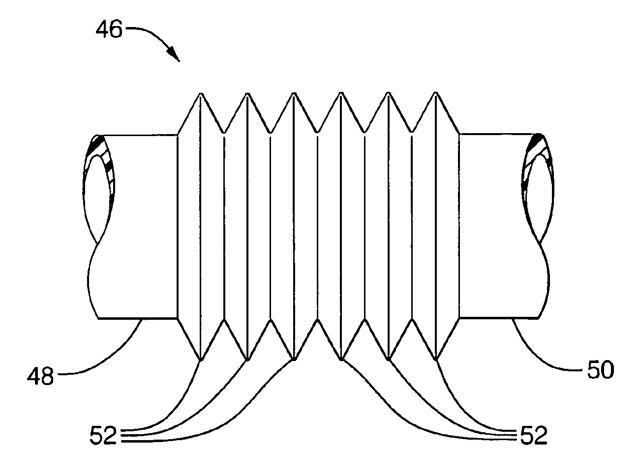
  • Claims
  • Application Information

AI Technical Summary

Benefits of technology

[0009]Briefly described, a fuel cell assembly or system in accordance with the invention includes flexible metal bellows elements in one or more tubes intended for carrying hot gases during operation of the assembly. Thermal expansion and contraction of the tubes, and of the non-tubular elements of the assembly, during start-up, running, and shut-down of the assembly can lead to buckling, cracking, and failure of the tubes, resulting in failure of the assembly or system. The flexible bellows elements, having relatively low axial and radial spring rates, or stiffness, thus are able to absorb thermal and vibrational dimensional changes, thereby protecting the rest of the assembly from potentially damaging stresses. In addition, because the bellows elements have relatively thin walls and relatively large wall area per linear unit of tubing, the corrugations provide significant resistance to axial heat flow and large radiant surface area, thus increasing thermal isolation where desired between relatively hot and relatively cold regions of the assembly.

Problems solved by technology

Thermal expansion and contraction of the tubes, and of the non-tubular elements of the assembly, during start-up, running, and shut-down of the assembly can lead to buckling, cracking, and failure of the tubes, resulting in failure of the assembly or system.

Method used


Image

  • Thermal and vibrational break for high-temperature gas tubes in a solid-oxide fuel cell
  • Thermal and vibrational break for high-temperature gas tubes in a solid-oxide fuel cell
  • Thermal and vibrational break for high-temperature gas tubes in a solid-oxide fuel cell

Examples


Embodiment Construction

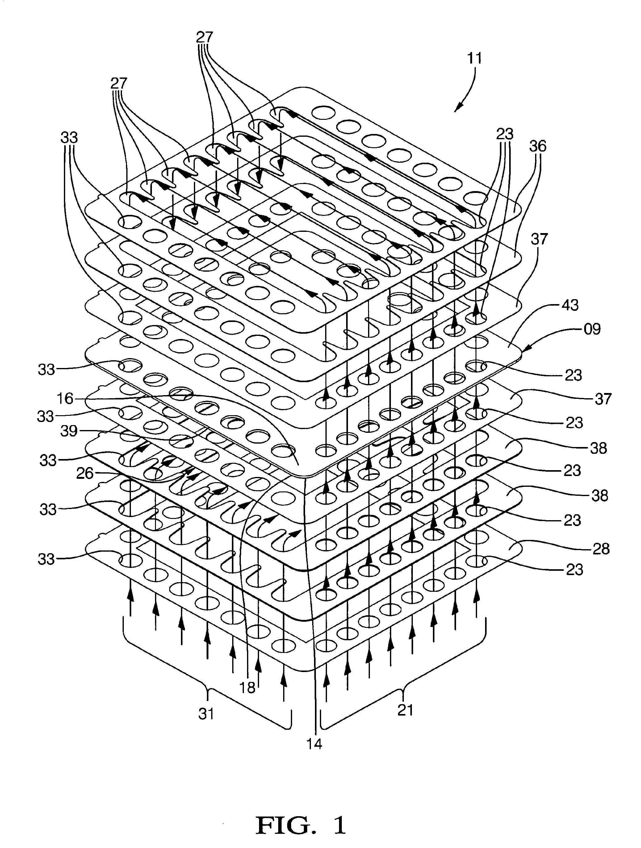
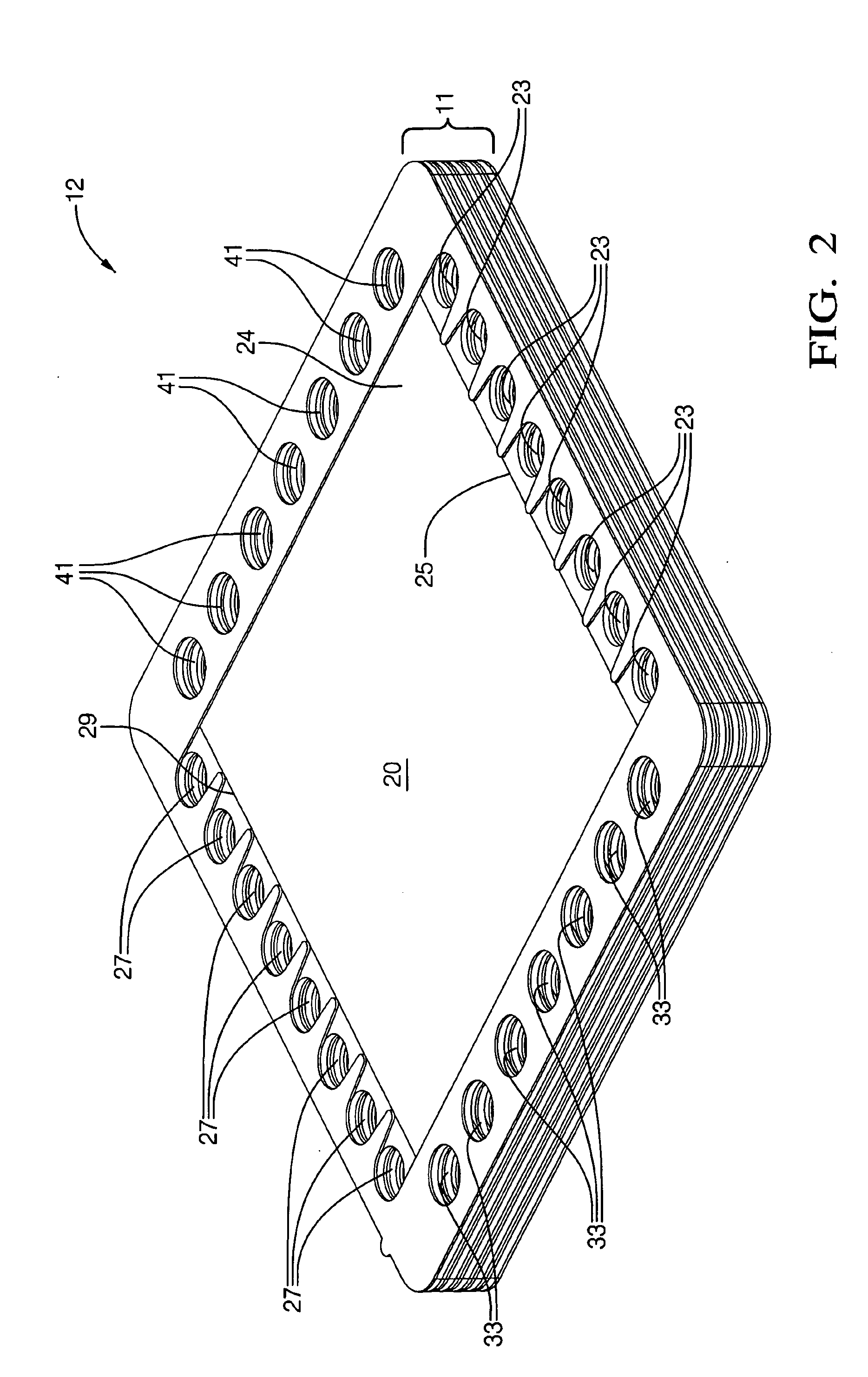
[0018]FIGS. 1 through 3 are useful in describing generally the structure of a multiple fuel cell stack assembly. FIGS. 4 and 5 are illustrative of improved fuel cell assemblies in accordance with the invention.

[0019]Referring to FIGS. 1 and 2, an individual fuel cell 11 includes a multilayer fuel cell element 09 comprising an electrolyte 14 (E) having an anode 16 or positive element (P) deposited on a first surface thereof and a cathode 18 or negative element (N) deposited on a second surface thereof. Thus, element 09, which is the actual “fuel cell,” is known in the art by the acronym PEN. Passage 24 for flow of fuel 21 across the free surface 20 of anode 16 is provided by first cut-out spacers 36 sealed to anode 16 by peripheral seal 37, and passage 26 for flow of air 31 across the free surface of cathode 18 is provided by second cut-out spacers 38 sealed to cathode 18 by another peripheral seal 37. Fuel 21, typically in the form of hydrogen or reformate gas, is provided at a firs...


PUM


Abstract

A fuel cell assembly or system including flexible metal bellows elements in one or more tubes intended for carrying hot gases during operation of the assembly. The bellows elements include a tubing element having plurality of annular corrugated folds. Thermal expansion and contraction of rigid tubes and of the non-tubular elements of the assembly can lead to buckling, cracking, and failure of the tubes and failure of the assembly or system. The flexible bellows elements, having relatively low axial and radial spring rates thus are able to absorb thermal and vibrational dimensional changes in the assembly. In addition, the corrugations provide significant resistance to axial heat flow and large radiant surface area, thus increasing thermal isolation where desired between relatively hot and relatively cold regions of the assembly.

Description

TECHNICAL FIELD[0001]The present invention relates to hydrogen / oxygen fuel cells; more particularly, to solid-oxide fuel cell assemblies and systems including piping for high-temperature gases; and most particularly, to solid-oxide fuel cell assemblies and systems wherein piping for high-temperature gases includes means for thermal and vibrational isolation of the high-temperature portion of the assembly from its surroundings.BACKGROUND OF THE INVENTION[0002]Fuel cells which generate electric current by the electrochemical combination of hydrogen and oxygen are well known. In one form of such a fuel cell, an anodic layer and a cathodic layer are deposited on opposite surfaces of an electrolyte formed of a ceramic solid oxide. Such a fuel cell is known in the art as a “solid oxide fuel cell” (SOFC). Hydrogen, either pure or reformed from hydrocarbons, is flowed along the outer surface of the anode and diffuses into the anode. Oxygen, typically from air, is flowed along the outer surf...

Claims


Application Information

Patent Timeline
IPC IPC(8): H01M2/00H01M2/14B60L11/18H01M8/02H01M8/04H01M8/06H01M8/10H01M8/12H01M8/18H01M8/24
CPCH01M8/0247H01M8/04007H01M8/2425H01M8/04089Y02E60/50H01M8/2483H01M8/2432
Inventor RICHARDSON, CURTIS A.HALTINER, JR., KARL J.KELLY, SEAN M.EDLINGER, BERNARD
Owner BAYERISCHE MOTOREN WERKE AG
Learn More