Method for butt-end electromechanical splicing

a technology of electromechanical splicing and butt-end, which is applied in the direction of electrically conductive connections, cable installation apparatus, electrical equipment, etc., can solve the problems of accelerated wear and tear of the cable itself, unable to reuse the cable in the case of hole operation, and gaps in the armor

Inactive Publication Date: 2000-11-21
BEAUFRAND EMMANUEL MARIE EUGENE
View PDF19 Cites 2 Cited by
  • Summary
  • Abstract
  • Description
  • Claims
  • Application Information

AI Technical Summary

Benefits of technology

The second object of this invention is to provide a method of repairing and splicing electromechanical cables that eliminates welding spot lumps at the spliced wire ends.
The third object of this invention is to provide a method of repairing and splicing electromechanical cables that eliminates the risk of exposure of spliced wire ends.
The fifth object of this invention is to provide a method of repairing and splicing electromechanical cables that allows the repaired cables to be used in high pressure cased hole operations.
Spliced cable using this process maintains its original characteristics and does not suffer any deformation that could restrain its use. Therefore, after being spliced, repaired cables can be reinstalled in cased hole logging operations, flow control pipes, pressure control systems in producing wells, high pressure cased hole operations as geothermal wells, steam injection wells, and the like, which represents an increased service life of the cable.
(iii) Post-forming the spliced cable to guarantee the effectiveness of the welding and to withdraw stress from the wires using a commercial Postformer.

Problems solved by technology

Over time, because of wear, corrosion, bending, fatigue, torque, rotation, physical damage, etc., these cables present loose armor, gaps in armor, broken armor wires, electrical leakage or break down, etc., and are required to be repaired.
Although the silver brazing technique assures the tips of the cut wires will stay in place, it has several problems caused by the welding spots.
These rigid and non-bendable spots increase the friction of the cable within logging holes, which accelerates the wear and tear of the cable itself.
Furthermore, the welding spots produce lumps that increase the diameter of the cable making it impossible to reuse it in cased hole operations since the lumps can cause the cable to get stuck in the pipe.
Although the shiming technique allows the spliced wires to retain their individual flexibility, this technique also has serious drawbacks.
For example, cables having the foil repair cannot be used in cased hole operations since typical high-pressure flow from the well would displace the foils exposing and allowing the tip ends of the cut wire to separate.
However, none of the patents overcome all the problems mentioned above.
Nevertheless, since butt-end welding applied to the outer armor wires binds the formation of arcs approximately one foot high at each wire splicing point which alters the original configuration of the electromechanical cable, this technique has not been used.

Method used


Image

  • Method for butt-end electromechanical splicing
  • Method for butt-end electromechanical splicing
  • Method for butt-end electromechanical splicing

Examples


Embodiment Construction

Before explaining the disclosed embodiment of the present invention in detail it is to be understood that the invention is not limited in its application to the details of the particular arrangement shown since the invention is capable of other embodiments. Also, the terminology used herein is for the purpose of description and not of limitation.

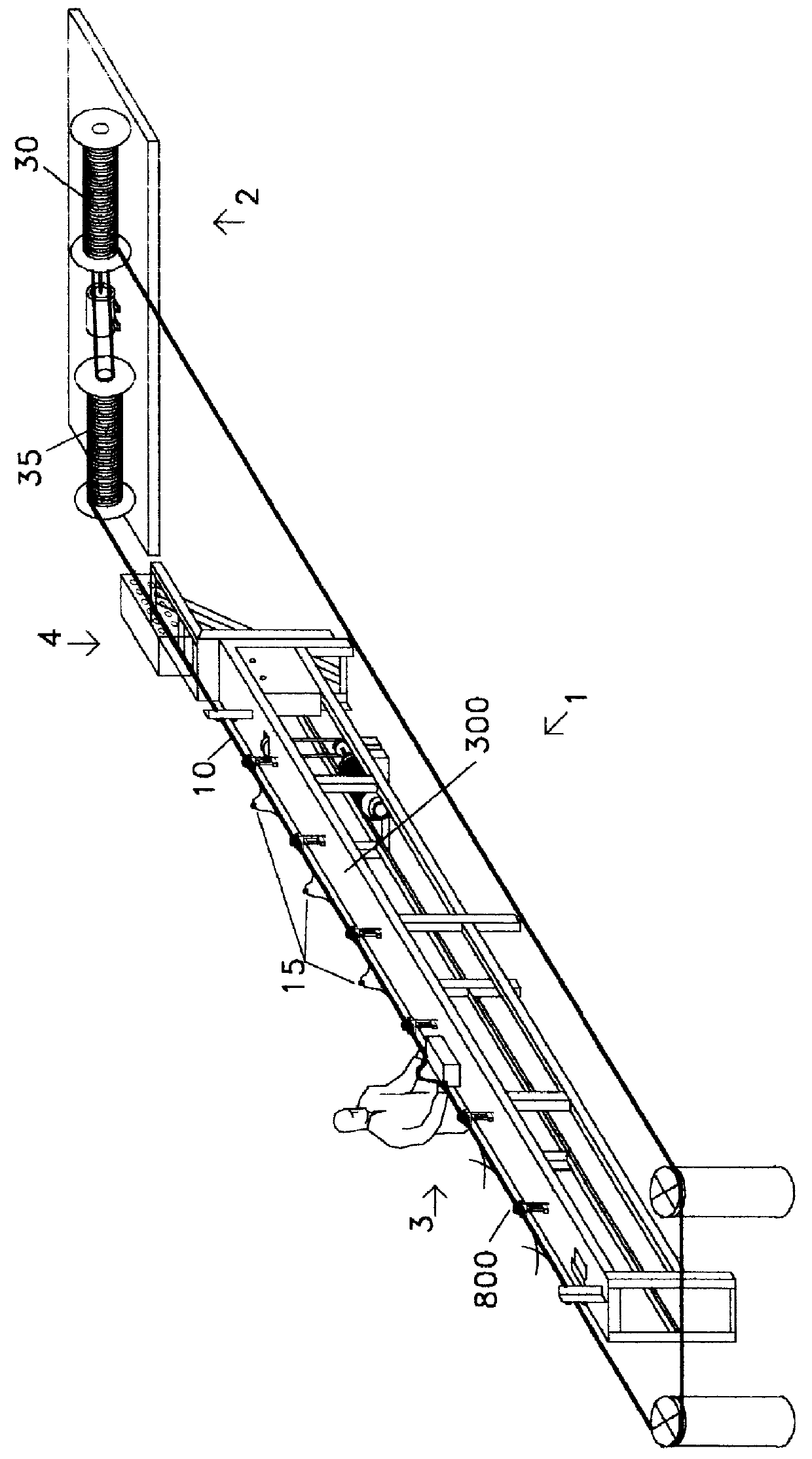
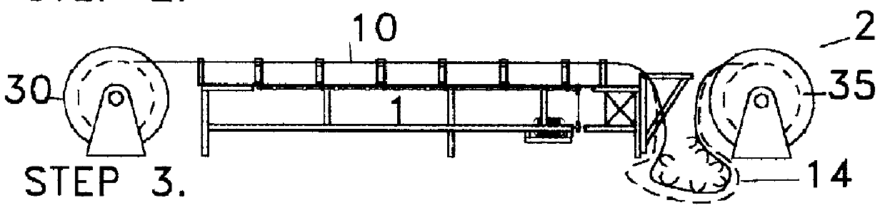
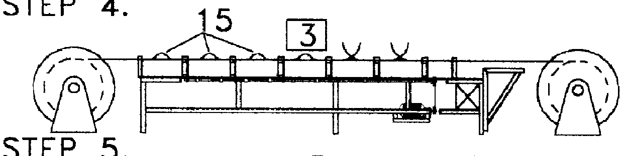
1 Arc Vanishing Machine, AVM FIG. 1E

The Arc Vanishing Machine 1 consists of 4 major groups of components: the support assembly 100 that provides the bearing structure for the other major components. The turrets assembly 600 with the former heads 800 on top where the vanishing of the arcs 15 takes place. The rotary system 1700 that gives the former heads 800 their spinning motion. The electrical system 1800 that controls the spinning motion of the former heads 800 and contains the security system 1600 that may stop the spooling of the cable 10.

The Support Assembly 100 is composed of framework 200, table surface 300, cable guides 400, and tran...


PUM

PropertyMeasurementUnit
lengthaaaaaaaaaa
lengthaaaaaaaaaa
stressaaaaaaaaaa

Abstract

A process and system for repairing electromechanical cables having an external armor wire layer using a butt welding technique and an arc vanishing machine. A short (break) in a cable having both an external and inner helically wrapped wire layer over an inner conductor(s) is located using conventional techniques. After the inner conductor(s) and inner wrapped layer are repaired (i.e., spliced), the outer wire layers are reconnected using a butt-end welding process and form individual arc shapes. The cable automatically passes through dies on headers to vanish (displace) each of the arcs to the end of the cable. A safety system activates an alarm to shut down the system when a jam occurs before any cable wires break. The system is reactivated after the jam is cleared.

Description

This invention relates to cables and in particular to a method of splicing electromechanical cables using a novel cable splicing technique of butt end welding and subsequent displacement of the wires conforming the outer armor of the cable with a machine designed for this purpose.BACKGROUND AND PRIOR ARTTraditional electromechanical cables are comprised of a core containing one or more insulated electric conductors and covered by two layers of helical pattern oppositely wound steel armor wires. Typically, the inner layer of wires in contact with the insulation material is wrapped in a right-hand lay. The outer layer of wires, to overcome the tendency of the cable itself to rotate, is wrapped over the inner layer in a left-hand lay pattern. These cables are used in the oil exploration industry for detonating explosives to "open" a field and in well logging operations. Over time, because of wear, corrosion, bending, fatigue, torque, rotation, physical damage, etc., these cables presen...

Claims


Application Information

Patent Timeline
Patent Type & Authority Patents(United States)
IPC IPC(8): H02G1/00H02G1/16
CPCH02G1/16Y10T29/49718Y10T29/49742Y10T29/49195
Inventor BEAUFRAND, EMMANUEL MARIE EUGENE
Owner BEAUFRAND EMMANUEL MARIE EUGENE
Why Eureka
Try Eureka