Thermal cycle engine boost bridge power interface

a technology of power interface and thermal cycle engine, which is applied in the control system, ac motor control, hot gas positive displacement engine plant, etc., can solve the problem of load consuming electrical power produced by the alternator, and achieve the effect of optimizing power transfer

Inactive Publication Date: 2005-03-29
THE BOEING CO
View PDF6 Cites 47 Cited by
  • Summary
  • Abstract
  • Description
  • Claims
  • Application Information

AI Technical Summary

Benefits of technology

The present invention is directed to a system and method for controlling a thermal dynamic cycle engine in optimal power transfer, with a maximum power factor, over varying life portions of the thermal dynamic cycle engine. The system generally operates to sense various portions and loads on the engine and provides for an optimal load, EMF, and various other physical attributes to provide for an optimal power transfer from the thermal dynamic cycle engine to a collection source. Ge

Problems solved by technology

A load consumes electrical power produ

Method used


Image

  • Thermal cycle engine boost bridge power interface
  • Thermal cycle engine boost bridge power interface
  • Thermal cycle engine boost bridge power interface

Examples


Embodiment Construction

The following description of various embodiments is merely exemplary and is in no way intended to limit the scope of the invention, its application, or uses. Furthermore, although the following description relates specifically to a thermal dynamic cycle engine using the Stirling cycle to produce power, it will be understood that any appropriate thermal dynamic engine may be used. For example, the invention may be equally well suited to operate and optimize a thermal dynamic cycle engine using the Brayton cycle or other appropriate thermal dynamic cycles. In addition, it will be understood that the invention may be used to optimize engines not specifically using thermal dynamic cycles but other appropriate power transfer or power production cycles.

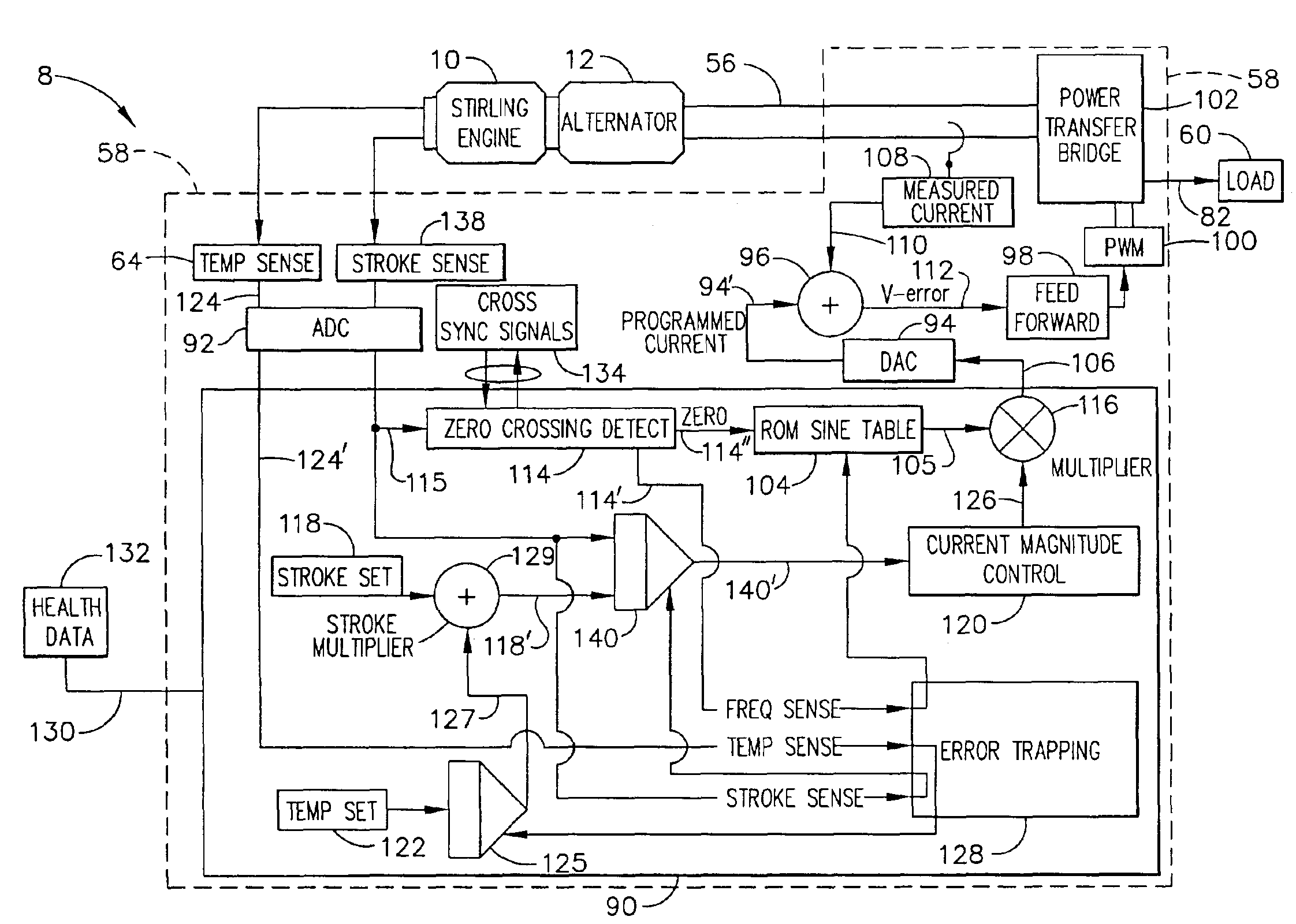
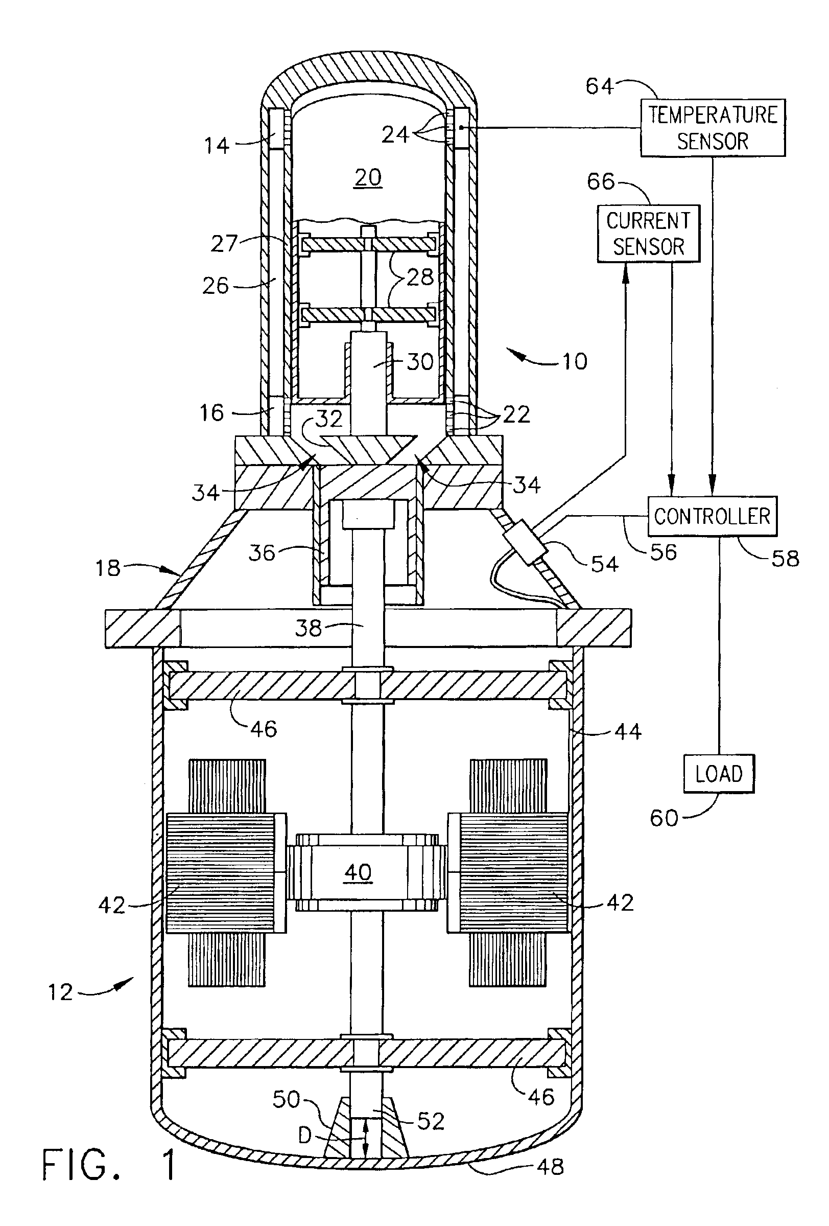
With reference to FIG. 1, a thermal dynamic cycle engine power creation and transfer system 8 is illustrated. The system 8 includes a Stirling cycle engine 10 that is operably interconnected with an alternator 12. In this way, mechanical en...


PUM


Abstract

A system and method for controlling a thermal dynamic cycle engine, such as a Stirling engine. The system includes a controller able to execute a program to alter certain aspects of the system to provide for a maximum power transfer and substantially stall free start up of the thermal dynamic cycle engine. Generally the controller is able to alter the current load to achieve a selected stroke length, pattern or temperature of a heater head of the engine. The system allows for generally stall free start-up and continuous control for maximum power (with maximum power factor) transfer from the thermal cycle engine or the associated alternator.

Description

FIELD OF INVENTIONThe present invention relates generally to control systems for mechanical engines; and particularly to a control system for use in a thermal engine with an alternator.BACKGROUND OF THE INVENTIONIt is generally known to provide an engine that can be powered by various non-chemical and mechanical means. For example, thermal differences may be used to power an engine to provide the thermal dynamic sources producing mechanical and electrical power through an alternator. The thermal dynamic engines include various thermal dynamic cycles which are harnessed to provide the mechanical energy for various engines. Various cycles include Stirling cycles, brayton cycles, and rankine cycles. These various cycles can be employed in engines using the same or similar name as the engine.Generally, each of these engines provide for producing energy from one of the related thermal dynamic cycles. The thermal dynamic cycles and the related engines require a differential in thermal ene...

Claims


Application Information

Patent Timeline
IPC IPC(8): F02G1/045F02G1/00F02G1/043
CPCF02G1/043H02P25/027H02P9/02F02G1/045H02P25/032
Inventor LYNCH, THOMAS H.KOCH, BRIAN
Owner THE BOEING CO
Why Eureka
Try Eureka