Method, impact machine, and equipment included in an impact machine

a technology of impact machine and equipment, which is applied in the direction of forging hammers, press, shaping presses, etc., can solve the problems of not being able to perform the manufacture in a rational mode according to prior art, affecting the quality of the finished product, and a great risk of damage, etc., to achieve the effect of high strength and high strength

Inactive Publication Date: 2005-03-29
MORPHIC TECH
View PDF13 Cites 16 Cited by
  • Summary
  • Abstract
  • Description
  • Claims
  • Application Information

AI Technical Summary

Benefits of technology

It is the purpose of the invention to address the above complex of problems, wherein it is a first object of the invention to provide a method and an equipment included in an impact machine, which allows a rational manufacture of annular articles of a formable working material. It is also an object to provide a technique which makes it possible to push out the formed product from its mould cavity without damaging the product. The invention particularly aims at making

Problems solved by technology

However, it is a problem to get the formed body out of the mould cavity without damaging it.
Therefore, it is a particularly great risk for damages when articles are manufactured, which are formed of powder, but also articles which are formed of a solid blank can crack or form layers, when they are pushed out of the mould cavity.
Besides, it has not

Method used


Image

  • Method, impact machine, and equipment included in an impact machine
  • Method, impact machine, and equipment included in an impact machine
  • Method, impact machine, and equipment included in an impact machine

Examples


embodiment

According to FIGS. 11-12

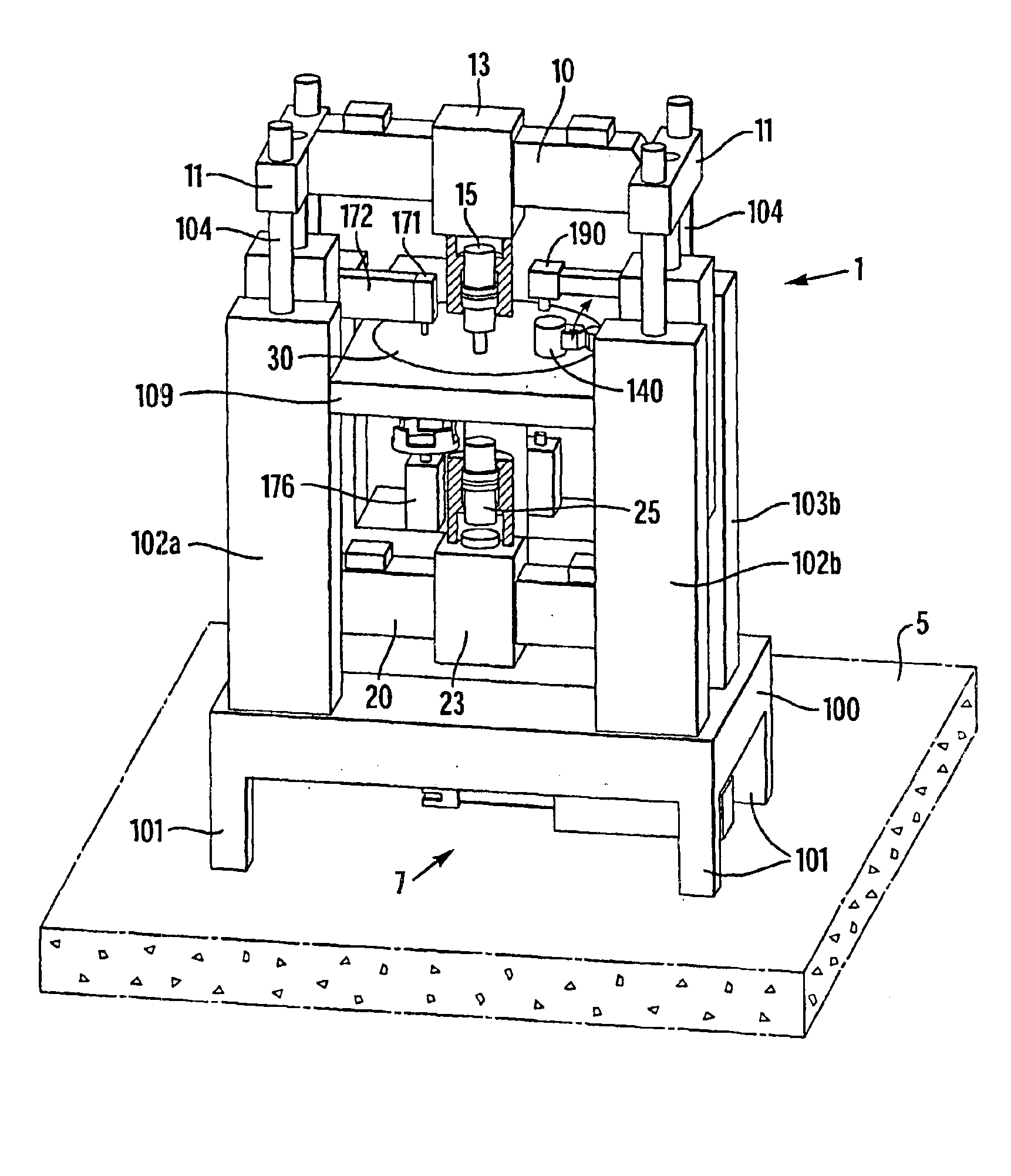
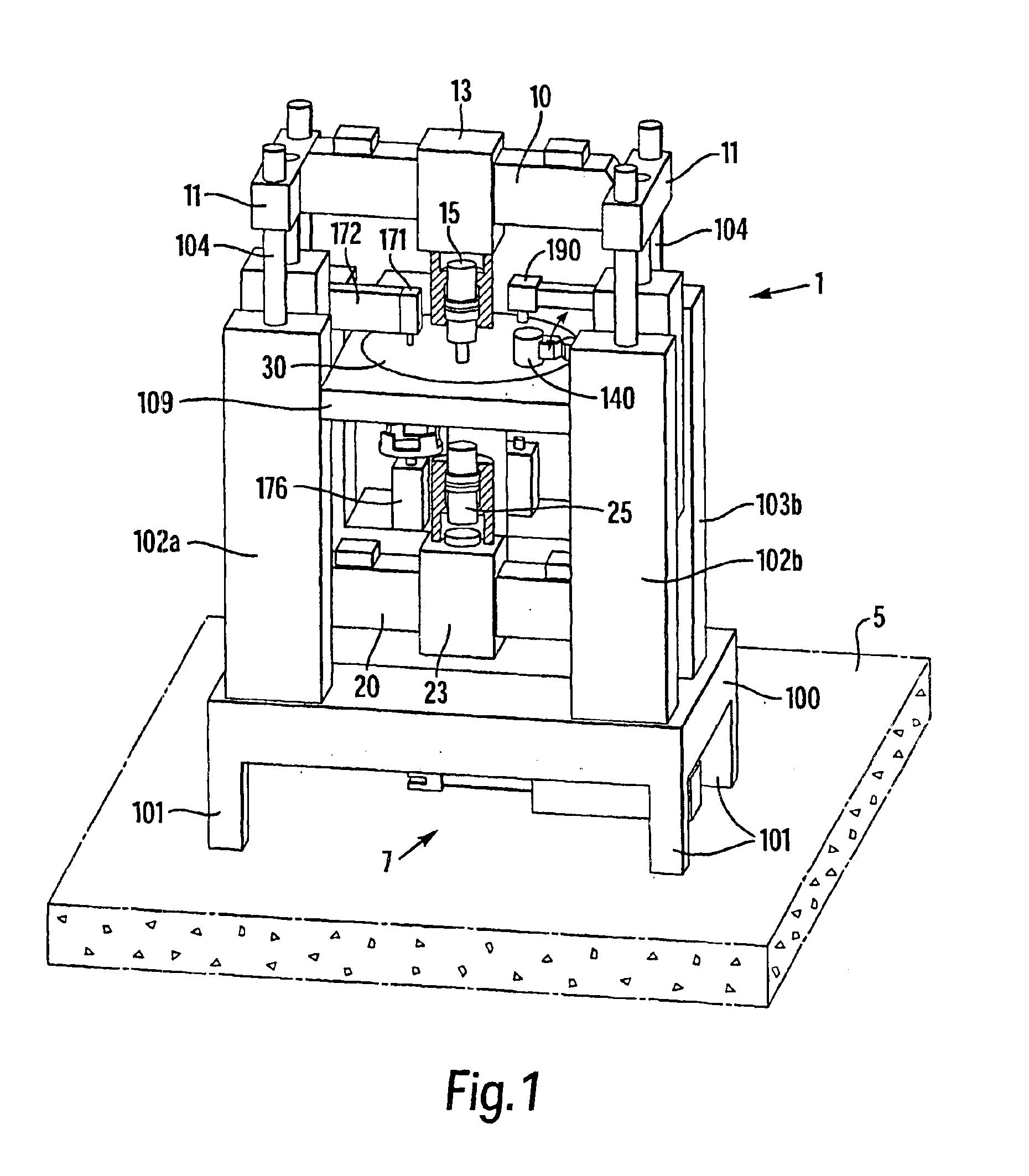
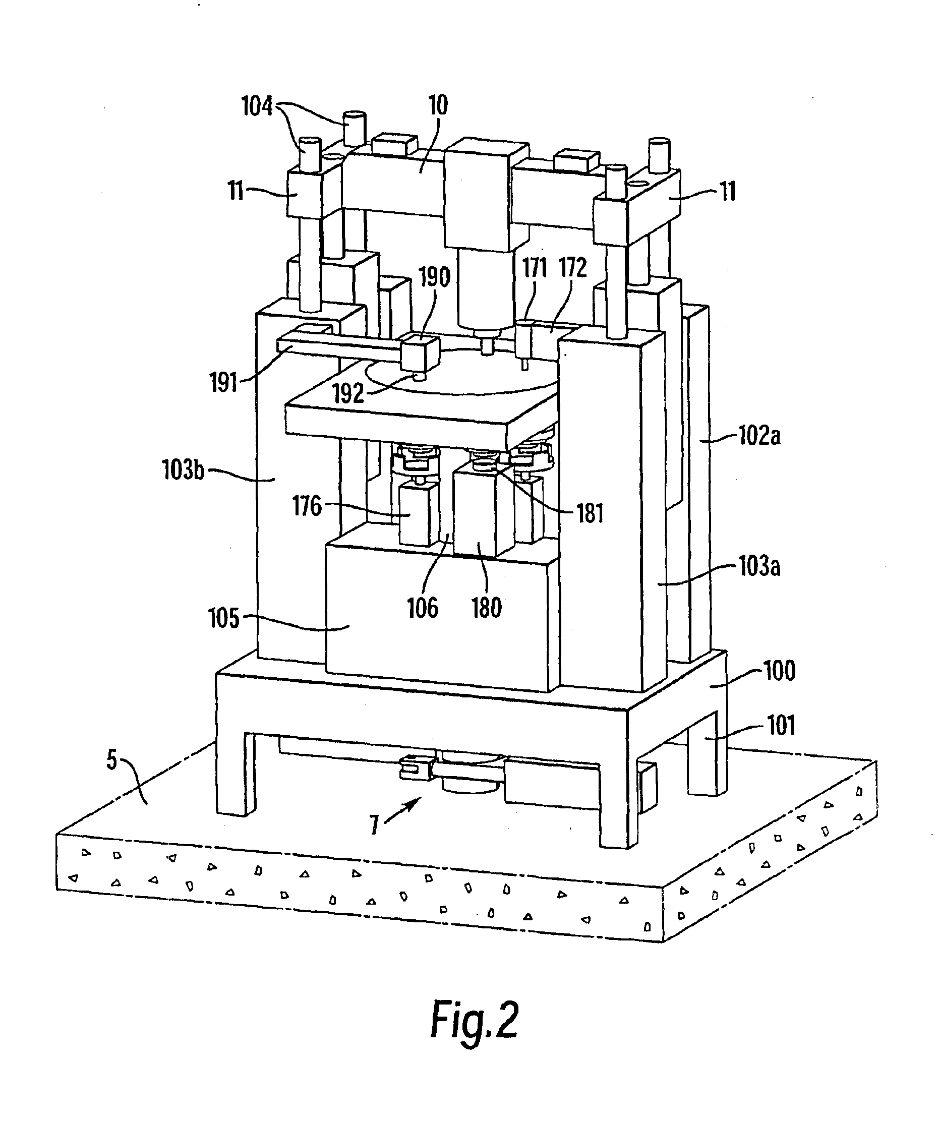
An impact machine 1″ is shown in FIG. 11. Its main parts consist of an upper impact unit 2, a lower impact unit 3 and a central unit, which comprises a tool carrier 30″. The latter one, according to the embodiment, consists of a horizontal table, which forms a shuttle, which is movable between two function stations; a forming station and a preparation station. The shuttle 30″ carries only one tool unit 32″, which is movable between the two function stations. During the movement between the function stations, the shuttle 30″ slides on a pair of horizontal guides 307, which are mechanically and rigidly connected to a machine stand 301 via arms 308.

In the forming station, the upper impact unit 2 has an upper ram 14 and the lower impact unit 3 has a lower ram 24.

In the preparation station, which is located further back in the view according to FIG. 11, the formed product shall be ejected out of the die in the tool unit 32″. As a holder-up at the ejection operatio...


PUM

PropertyMeasurementUnit
Pressureaaaaaaaaaa
Velocityaaaaaaaaaa

Abstract

The invention relates to a method for the manufacture of an annular article, which substantially consists of metal, ceramic material, and/or polymer. A cavity in a die is filled with a formable working material, which shall form said article. A tubular, upper punch (17) is introduced into the upper mouth of a hole in a die (34), so that a closed mould cavity is formed. The upper punch and a lower punch (27) are simultaneously struck towards one another at such a high velocity that the working material is plasticized and flows out and fills the mould cavity, and thereafter the upper punch is removed. Then, a mandrel (35) in the lower punch is driven out of the annular body by means of a mandrel expulsor (170), which is pressed against the mandrel from above, and thereafter the annular body is from below pushed out of the die by mean of the lower punch. The invention also relates to an equipment for the carrying out of the method.

Description

TECHNICAL FIELDThe invention relates to a method for the manufacture of an annular article, which substantially consists of metal, ceramic material, and / or polymer. The invention also relates to an equipment included in an impact machine for the manufacture of an annular article, which substantially consists of metal, ceramic material, and / or polymer, and to the impact machine in which the equipment is included.BACKGROUND OF THE INVENTIONImpact machines for working by the employment of high kinetic energy are machines for working in the first place metal, such as cutting, punching, and plastic forming of powder components, powder compaction, and similar operations, in which the velocity of a ram, which may consist of a hydraulic piston, may be essentially higher than in conventional presses. Also polymeric and ceramic working materials can be conceived, as well as various composites of metals, polymers and ceramic materials. The working principle is based on the development of a ver...

Claims


Application Information

Patent Timeline
IPC IPC(8): B22F3/17B22F3/03B22F3/00B21J9/02B21J13/03B21J5/06B21J5/12B21J7/34B21J13/02B21J7/28B21J9/00B21J7/00B30B11/02B30B11/08
CPCB21J5/12B21J7/28B21J7/34B21J9/02B21J13/03B22F3/03B30B15/026B30B11/005B30B11/027B30B11/08B22F3/17B29C33/20B29C2043/3618B29C2043/5833
Inventor OLSSON, H.ANG.KAN
Owner MORPHIC TECH
Why Eureka
Try Eureka