Spectacle lens and manufacturing method therefor

a technology of spectacles and lenses, applied in the field of spectacle lenses, can solve problems such as not addressing the overall wearing conditions

Inactive Publication Date: 2005-03-29
HOYA CORP
View PDF22 Cites 39 Cited by
  • Summary
  • Abstract
  • Description
  • Claims
  • Application Information

AI Technical Summary

Benefits of technology

By providing comparative information in this manner, it becomes possible to cancel the selection of an individually designed product and purchase a standardized product when there is not much difference between an individually designed product and a standardized product.

Problems solved by technology

Therefore, the disclosure in the publication only emphasizes the accurateness of a near use prescription, and does not address overall wearing conditions for lenses such as spherical design lenses, aspherical single vision lenses, and bifocal lenses.

Method used


Image

  • Spectacle lens and manufacturing method therefor
  • Spectacle lens and manufacturing method therefor
  • Spectacle lens and manufacturing method therefor

Examples


Embodiment Construction

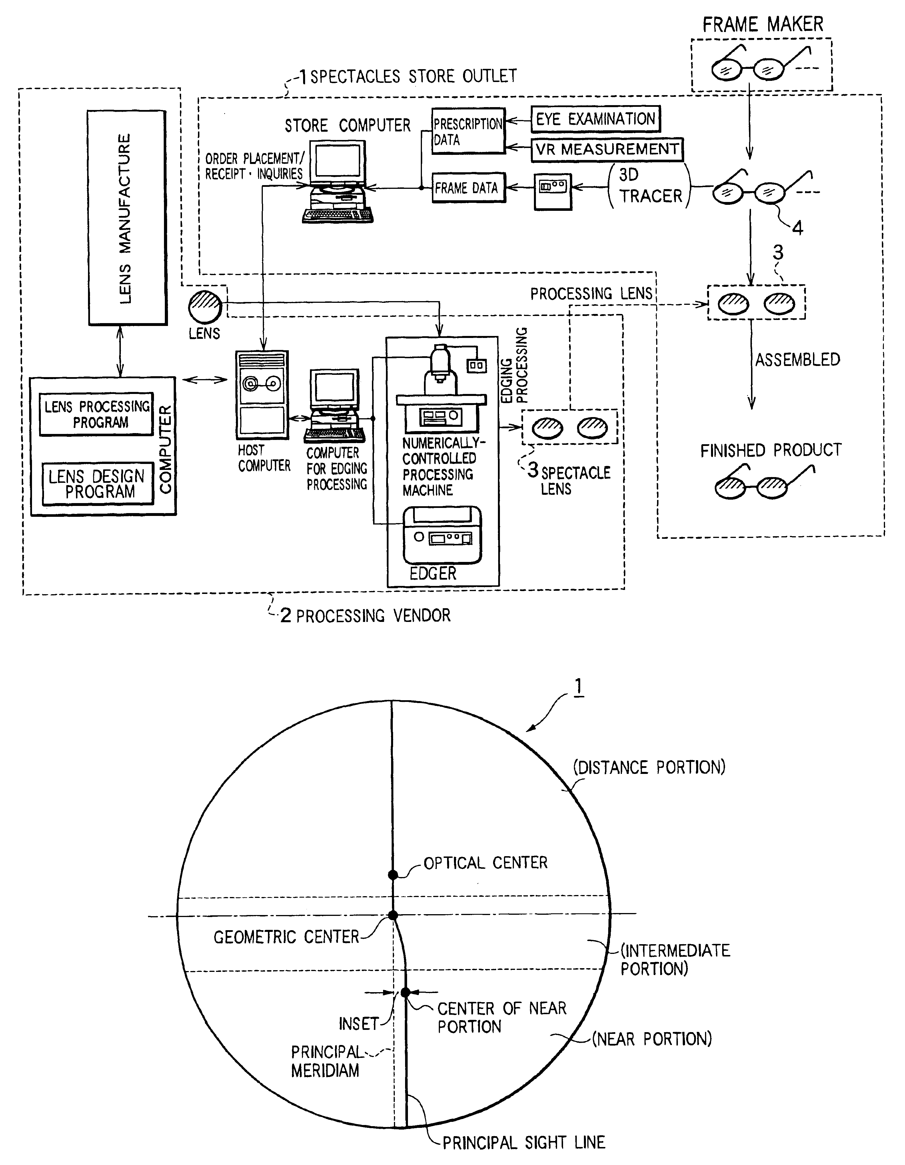
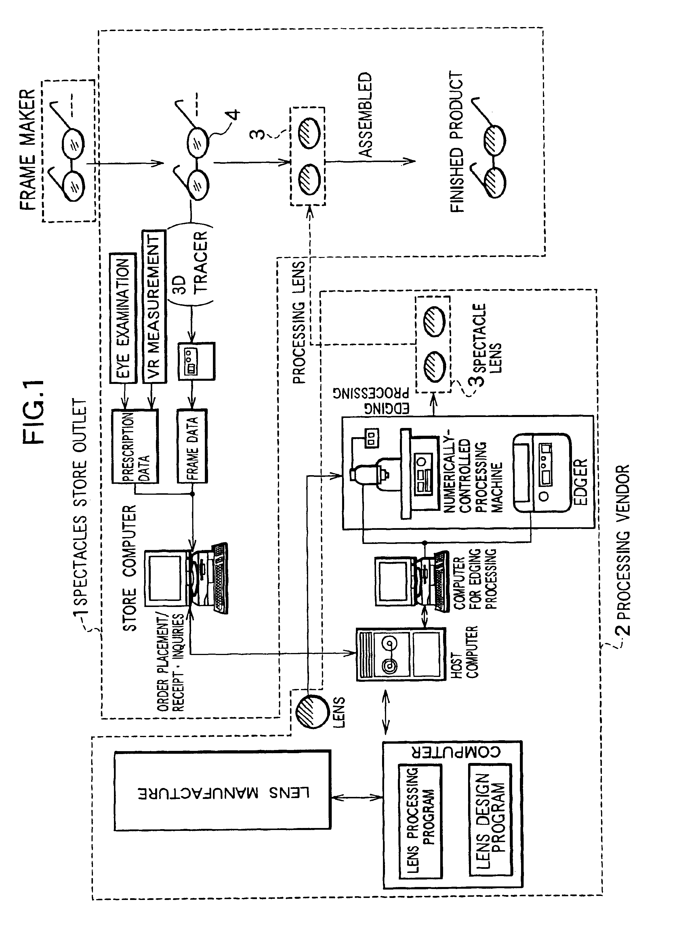
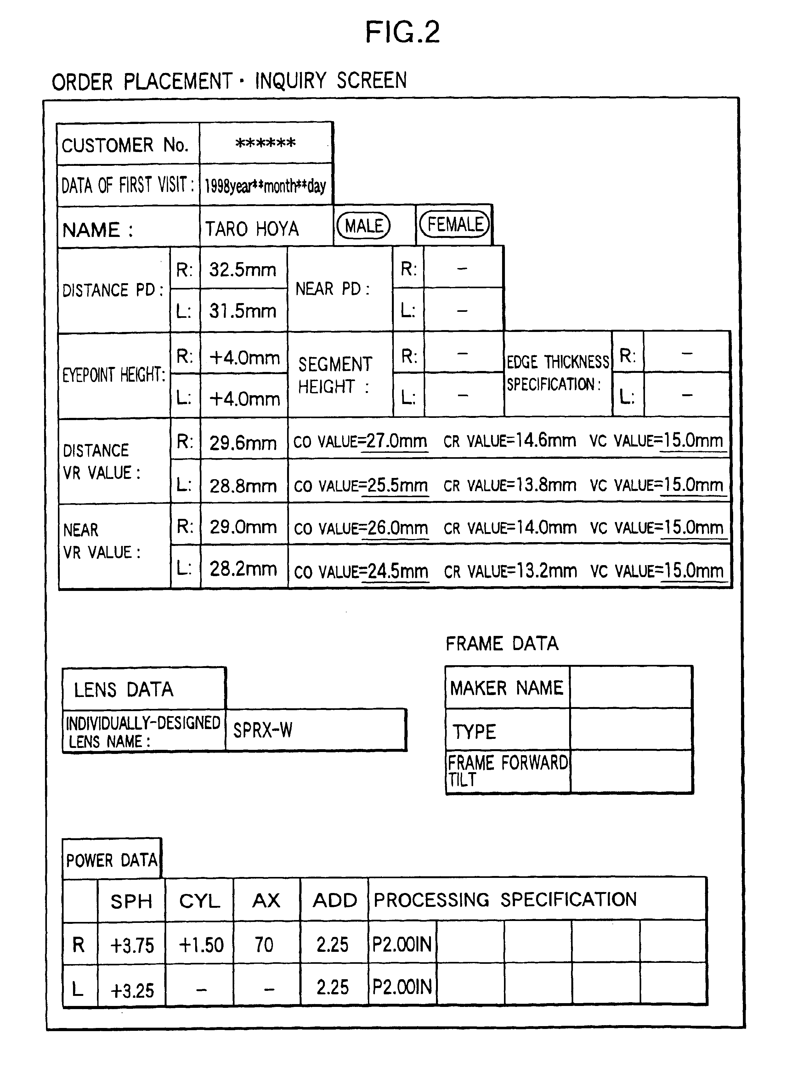
Aspects of the embodiment of the present invention will be explained hereinbelow based on the figures. FIG. 1 is a schematic diagram of a manufacturing method of a spectacle lens related to an aspect of the embodiment of the present invention, FIG. 2 is a schematic diagram of an ordering screen, FIG. 3 is a flowchart of a manufacturing process of a spectacle lens, and FIG. 4 is a schematic diagram of an optical model of spectacles wearing.

In FIG. 1. Reference Numeral 1 is a spectacles store (ordering party), and Reference Numeral 2 is a spectacles processor (processing party). The spectacle lens manufacturing method of this aspect of the embodiment is such that a spectacle lens 3 is designed and manufactured based on information sent via a terminal apparatus installed at the spectacles store (ordering party) 1 to an information processing system installed at the processor (processing party) 2.

That is, via the above-mentioned terminal apparatus there is sent to the above-mentioned in...


PUM


Abstract

A spectacle lens is designed by using a value determined by either measuring or specifying for an individual spectacles wearer the value of the distance VR from a reference point on the back surface of a spectacle lens to the center of rotation of the eye, which adds together the value of the distance VC from a reference point of the back surface of a spectacle lens to the vertex of the cornea of the eye of the spectacles wearer at spectacle lenses wearing time, which is one of the required data in spectacle lens design, and the distance CR from the above-mentioned vertex of the cornea to the center of rotation of the eye, and manufacturing a spectacle lens based on this design specification.

Description

BACKGROUND OF THE INVENTION1. Field of the InventionThe present invention relates to a spectacle lens, which is designed and manufactured taking into consideration the distance between the center of rotation of the eye and a spectacle lens of an individual spectacles wearer, and a manufacturing method therefor.2. Description of the Related ArtDespite the fact that spectacle lenses comprises single vision lenses and multifocal lenses (including progressive-power lenses) with different optical characteristics, they are generally designed on the basis of certain average utilization conditions. An example in which individual utilization conditions are taken into consideration is the method disclosed in Japanese Patent Application Laid-open No. 6-18823, in which there is proposed a progressive-power lens designed in consideration of individual utilization conditions, and there is disclosed the use of an aspheric surface, which is not accompanied by point symmetry axial symmetry in a pres...

Claims


Application Information

Patent Timeline
Patent Type & Authority Patents(United States)
IPC IPC(8): G02C13/00
CPCG02C7/027G02C7/028G02C13/003G02C7/061G05B2219/45175G05B2219/36384G02C7/02
Inventor YAMAKAJI, TETSUMAHATANAKA, TAKASHI
Owner HOYA CORP
Why Eureka
Try Eureka