Controlled deployment of a medical device

a medical device and control technology, applied in the field of controlled deployment of medical devices, can solve problems such as the possibility of rupture, and achieve the effect of improving the control of balloon inflation and improving the results

Inactive Publication Date: 2005-03-29
BOSTON SCI SCIMED INC
View PDF9 Cites 383 Cited by
  • Summary
  • Abstract
  • Description
  • Claims
  • Application Information

AI Technical Summary

Benefits of technology

In another aspect, the invention features a method of performing angioplasty using a balloon catheter. The method includes providing a balloon catheter having an inflatable balloon on its exterior. The balloon is initially partially radially restrained against inflation by a slidable sheath which surrounds the balloon and is inflatable by injection of fluid through a lumen in the catheter. The sheath is adapted to slide axially along the balloon onto the catheter shaft in response to pressure in the balloon such that the balloon may be progressively incrementally inflated. The method further includes inflating an unrestrained portion of the balloon by injecting fluid into the balloon through a lumen in the catheter and then inflating a restrained portion of the balloon by injecting additional fluid into the balloon through the lumen such that the pressure of the fluid inside the balloon incrementally slides a restraining sheath off of the balloon, allowing the balloon to progressively incrementally inflate.
The inventions have many advantages. For example, it is often important to accurately position a prosthesis so that it is properly centered about the diseased area with the ends anchored on healthy tissue on either side of the area. Often, there is only a very short segment of healthy lumen on which the ends of the prosthesis may be anchored.
In angioplasty, a balloon catheter is used to widen an area of a lumen that is occluded, e.g., an artery occluded by plaque or intimal proliferation or a heart valve. The improved control over balloon inflation provided by this invention can improve the results which may be obtained in this area as well.

Problems solved by technology

This reduces the pressure in the aneurysm and hence, the likelihood that it will rupture.

Method used


Image

  • Controlled deployment of a medical device
  • Controlled deployment of a medical device
  • Controlled deployment of a medical device

Examples


Embodiment Construction

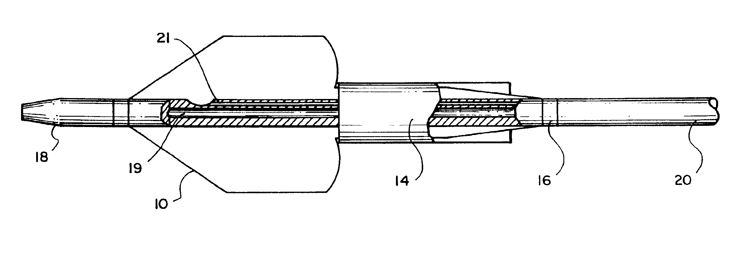
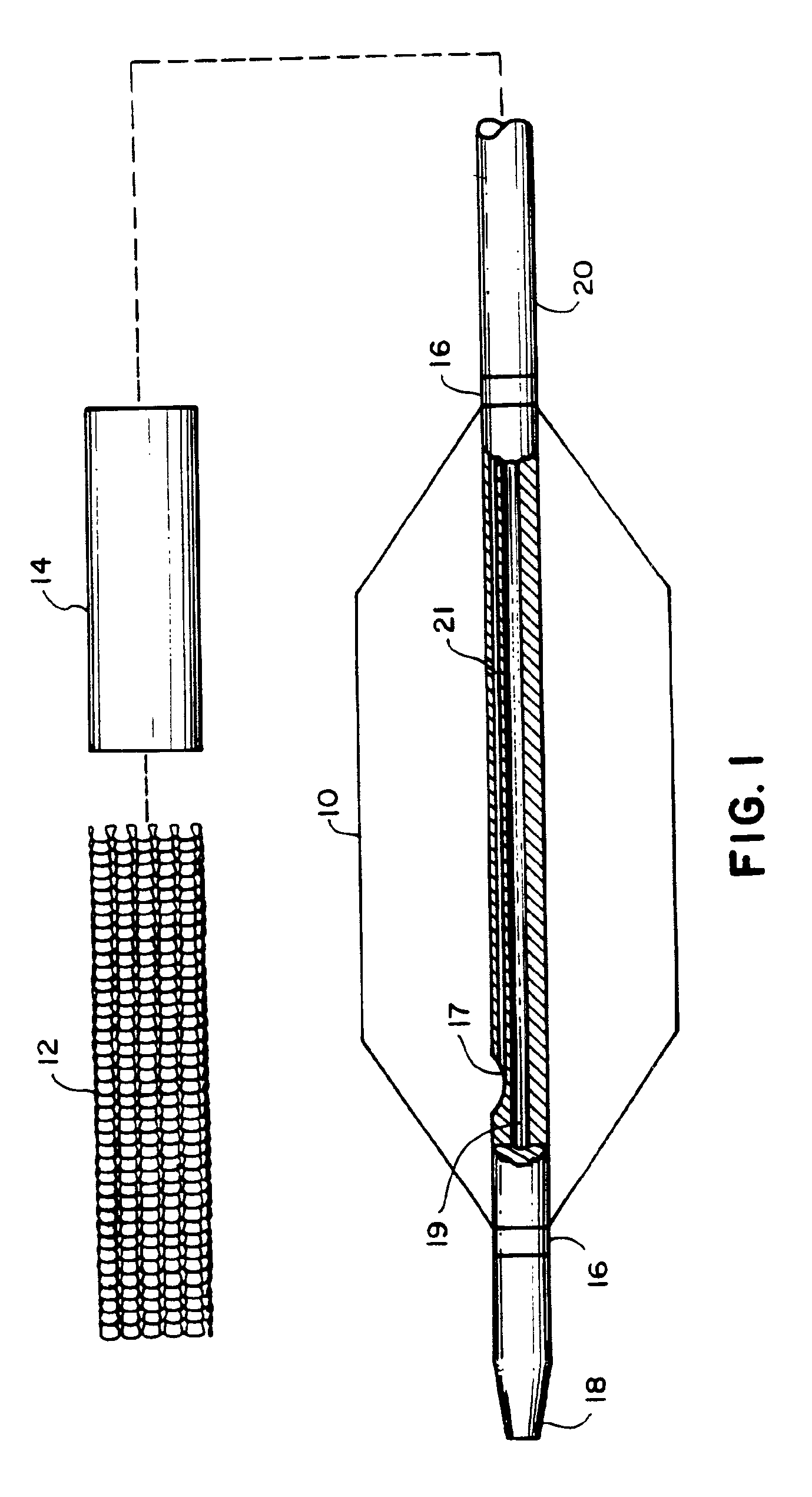
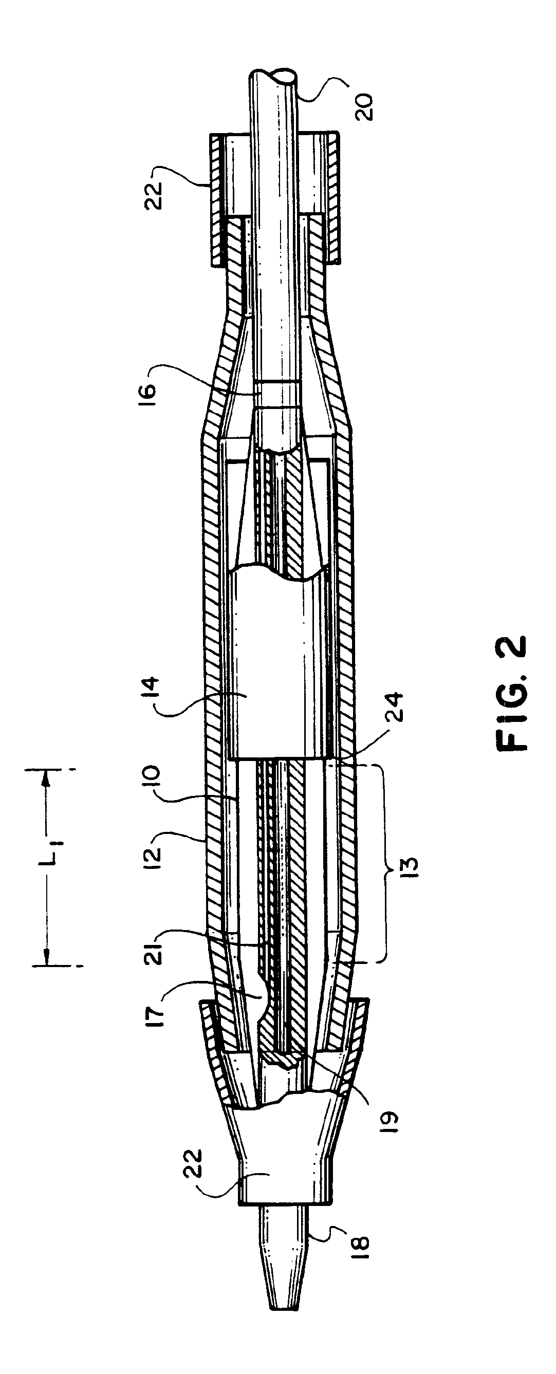
Referring to FIGS. 1 and 2, an embodiment of the invention for placement of an aortic graft includes a vascular catheter 20 carrying a balloon 10, an inflation constraint 14 in the form of an annular sheath, and a tubular prosthesis 12. Referring particularly to FIG. 2, for delivery into the body, balloon 10 is folded around the catheter body and constraint 14 is positioned so that a short distal portion 13 of the balloon remains unconstrained. Prosthesis 12, in a small diameter condition, is then slipped over this assembly such that it is disposed above the unconstrained distal portion 13 of the balloon and the constraint over the more proximal portions of the balloon. The prosthesis is held in place on both ends by sleeves 22. The balloon can be inflated by the introduction of inflation fluid through an inflation lumen 21 which communicates with the interior of the balloon via an inflation port 17.

As will be discussed in more detail below, controlled introduction of an initial vol...


PUM


Abstract

A prosthesis delivery system having a balloon catheter with an inflatable balloon on its exterior. The balloon is inflatable by injection of fluid through a lumen in the catheter and the balloon is initially partially constrained against inflation by a constraint. A tubular prosthesis is disposed on the catheter over at least a portion of the balloon and a portion of the constraint. The tubular prosthesis has a contracted condition and an expanded condition. The tubular prosthesis is initially disposed on the catheter in the contracted condition. Further, a balloon catheter includes a constraint so that the balloon may be sequentially inflated for dilatation purposes such as in a valvuloplasty operation.

Description

BACKGROUND OF THE INVENTIONThis invention relates to controlled deployment of medical devices such as endoprostheses and balloons.Prostheses are used in body lumens that have been occluded or weakened by disease. For example, to treat arterial stenoses, an endovascular stent is implanted to hold the lumen open and to prevent any flaps or dissections on the lumen wall from occluding the lumen. To treat aneurysms, a prosthesis in the form of a graft is attached to healthy portions of the lumen on either side of the aneurysm so that the body of the graft bridges the weakened area. The wall of these grafts is initially permeable, but through clotting action, becomes fluid impermeable. This reduces the pressure in the aneurysm and hence, the likelihood that it will rupture.Prostheses are typically delivered into the body on a catheter in small diameter form and then expanded to engage the lumen at the desired site. They may be self-expanding, i.e., they expand from a small diameter to a ...

Claims


Application Information

Patent Timeline
Patent Type & Authority Patents(United States)
IPC IPC(8): A61F2/06A61M25/10A61F2/84
CPCA61F2/958A61M25/10A61M25/1002A61M2210/125A61M2025/1068A61M2025/1081A61M2025/1059
Inventor ROBERTS, GEORGE T.HESS, KATHLEEN L.NOTT, SEPIDEH H.CHU, MICHAEL S. H.CHIN, YEM
Owner BOSTON SCI SCIMED INC
Why Eureka
Try Eureka