Differential time-to-threshold A/D conversion in digital imaging arrays

Inactive Publication Date: 2005-03-29
MURPHY CHARLES DOUGLAS
View PDF16 Cites 17 Cited by
  • Summary
  • Abstract
  • Description
  • Claims
  • Application Information

AI Technical Summary

Benefits of technology

It is an object of the present invention to provide a simple approach to eliminating certain types of fixed-pattern noise in digital imaging systems that use time-to-threshold techniques for A / D conversion.
It is another object of the present invention to shift the performance burden in high-precision time-to-threshold A / D conversion for digital imaging from precise component matching in large numbers of sensors and simple comparing circuits to precise matching of a small number of reference signal levels.

Problems solved by technology

Notwithstanding, none of the prior art on time-to-threshold A / D conversion in digital imaging takes into account the undesirable effects known as fixed-pattern noise (FPN).
Component parameter mismatch can result from manufacturing or age effects.
In CMOS, many circuit parameters depend on size ratios—for instance, transistor gains are functions of channel width-to-length ratios—so that size errors lead to component mismatch.
FPN is a particular problem in high-precision imaging systems, as the “noise” pattern may be much stronger than the weak incident energy variations which such systems aim to detect.
Initialization errors can occur when the pre-initialization state of a sensor affects the actual state reached during the finite initialization time.
Imaging systems with time-to-threshold A / D conversion may suffer from both FPN and input-dependent (i.e. incident energy dependent) errors.
A strong input may quickly exceed the threshold level and so over-drive the comparing circuit, resulting in a short delay.
A weak input signal may hover near the threshold level and so not over-drive the comparing circuit as much, resulting in a longer delay.

Method used


Image

  • Differential time-to-threshold A/D conversion in digital imaging arrays
  • Differential time-to-threshold A/D conversion in digital imaging arrays
  • Differential time-to-threshold A/D conversion in digital imaging arrays

Examples


Embodiment Construction

In the preferred embodiment of the invention, a first time-to-threshold conversion measurement and a second time-to-threshold conversion measurement are acquired using a first sensor and a first threshold-detecting circuit, but different initial sensor output values.

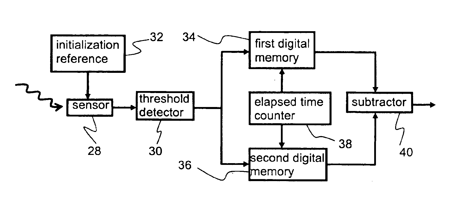
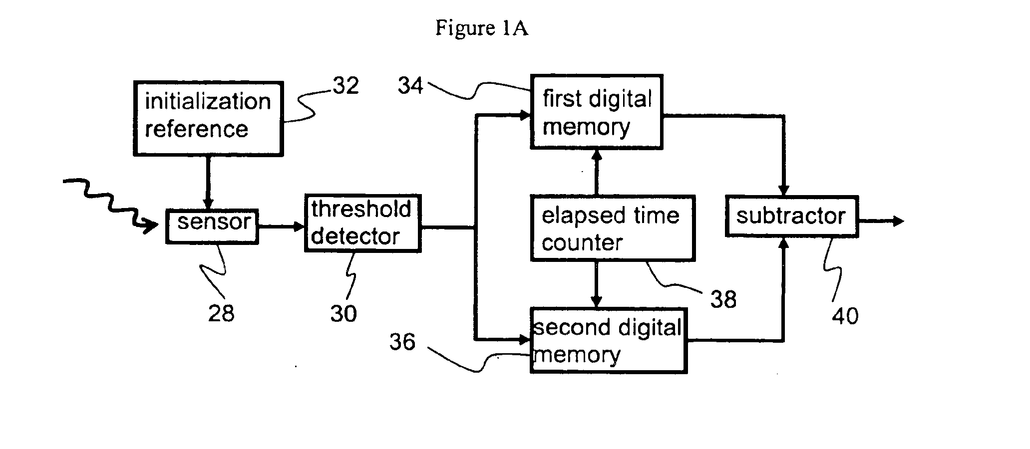
FIG. 1A shows a block diagram of a system for the preferred embodiment of the invention. First sensor 28 is connected to first threshold detector 30. For the first time-to-threshold measurement, first sensor 28 is initialized to a first initial output value on the basis of a reference signal supplied by initial sensor output reference 32.

The output of first threshold detector 30 is a digital indicator signal. It is passed to first digital memory 34 during the first measurement. First digital memory 34 records a first digital count value provided by digital counter 38 when the output of first threshold detector 30 indicates the threshold has been reached.

For the second measurement, the output of first sensor 28 is initial...


PUM


Abstract

Differential measurements allow correction of fixed-pattern noise errors in digital imaging arrays which use time-to-threshold A / D conversion techniques. Two time-to-threshold measurements are made with the same sensor and threshold-detecting circuitry. The measurements are made in quick succession so that the amount of incident energy is substantially unchanged. However, the two measurements use differing initial sensor output levels or threshold levels. The difference between the two measurements then reflects the time required for each sensor output signal to change by an amount equal to the difference between the initial sensor output values or the threshold values. Repeatable noise terms are cancelled in the computed difference measurement.

Description

CROSS-REFERENCE TO RELATED APPLICATIONSThe application is related to COMPARING CIRCUITS FOR TIME-TO-THRESHOLD A / D CONVERISON IN DIGITAL IMAGING ARRAYS filed by the applicant.STATEMENT REGARDING FEDERALLY SPONSORED RESEARCH OR DEVELOPMENTNot applicableREFERENCE TO A MICROFICHE APPENDIXNot applicableBACKGROUND1. Field of InventionThe invention relates to digital imaging using time-to-threshold A / D conversion, particularly to elimination of measurement errors due to different cells having mismatched components and being exposed to differing amounts of incident energy.2. Description of Prior ArtTime-to-threshold A / D conversion in digital imaging is well-known in the prior art. The approach is most useful in very large (by sensor count) imaging arrays with analog, mixed-signal, and digital logic circuits incorporated onto a single chip. The dominant technology for such systems is CMOS, a popular fabrication process that is widely used to make digital chips such as microprocessors and mem...

Claims


Application Information

Patent Timeline
IPC IPC(8): H03M1/34H03M1/50
CPCG04F10/005
Inventor MURPHY, CHARLES DOUGLAS
Owner MURPHY CHARLES DOUGLAS
Why Eureka
Try Eureka