Microlithographic reduction projection catadioptric objective

a technology of catadioptric objective and reduction projection, which is applied in the direction of instruments, photomechanical devices, optical elements, etc., can solve the problems of mounting and adjustment face difficulties, and achieve the effect of reducing the complexity of mounting and adjusting, and high imageside numerical apertur

Inactive Publication Date: 2005-03-29
CARL ZEISS SMT GMBH +1
View PDF49 Cites 104 Cited by
  • Summary
  • Abstract
  • Description
  • Claims
  • Application Information

AI Technical Summary

Benefits of technology

It is an object of the invention to provide a generic objective of good capabilities of chromatic correction for typical bandwidths of excimer laser light sources, which allows for a high imageside numerical aperture, and which reduces complexity of mounting and adjusting.

Problems solved by technology

However, all but one of the mirrors need to be cut off sections of bodies of revolution, so that mounting and adjustment face difficulties.

Method used


Image

  • Microlithographic reduction projection catadioptric objective
  • Microlithographic reduction projection catadioptric objective
  • Microlithographic reduction projection catadioptric objective

Examples


Embodiment Construction

An important concept of the present invention is to replace the front end of an “h-design” objective with a different front end that provides a single axis system.

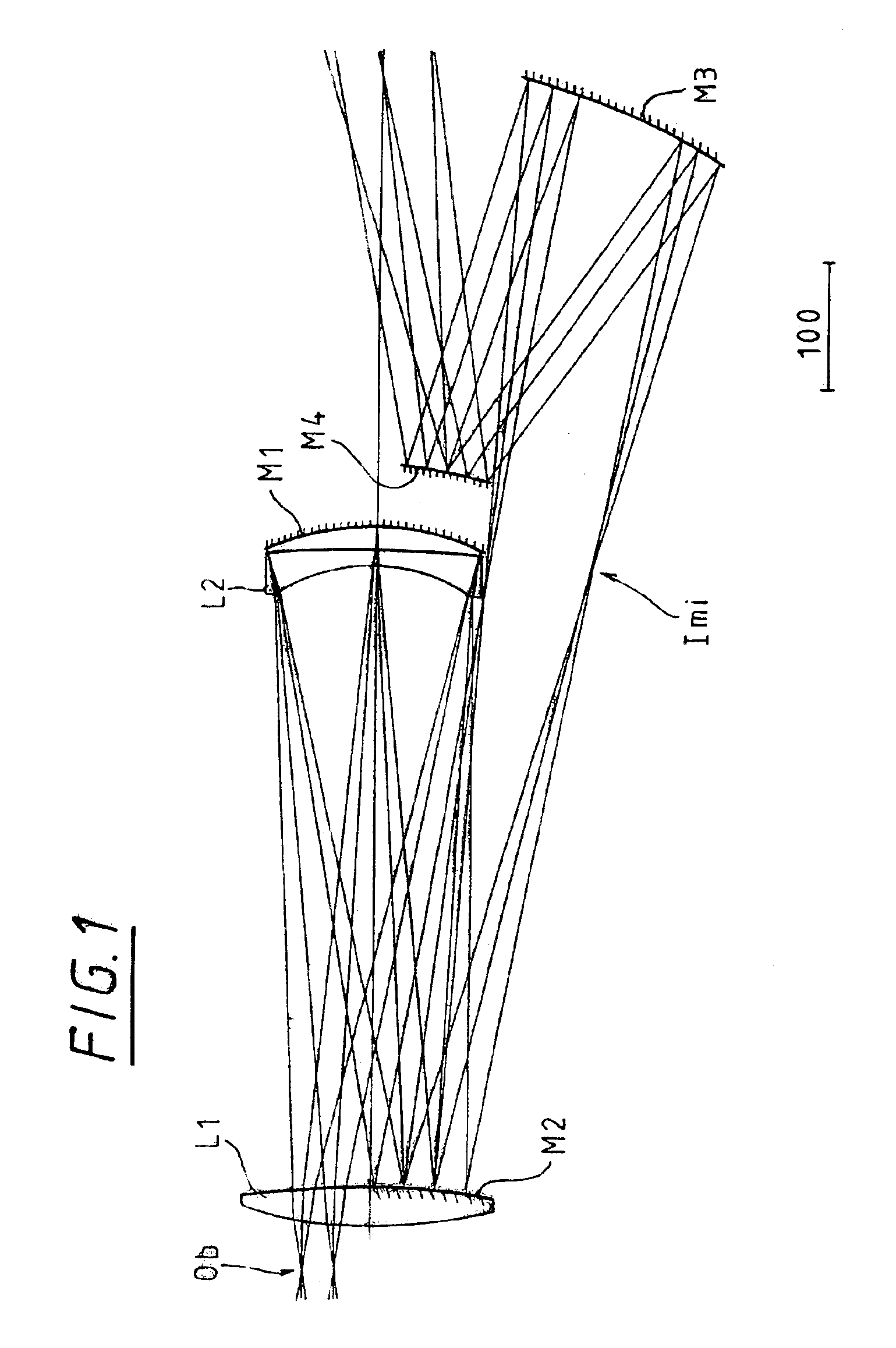
In the simplest version of this new front end, set up to be part of a −0.25 reduction, 0.75 image side NA system with a 7 mm ×26 mm rectangular image field size, the optical elements are shown in the lens section of FIG. 1. This catadioptric partial system provides a virtual image on the right hand side, which has enough a axial chromatic aberration to compensate for a conventional focusing lens group that forms a 0.75 NA image. A real pupil or aperture plane is formed on the right hand end of the system. The system shown has enough Petzval sum so that the focusing lens group can be made up mostly of positive power lenses.

There is only one field lens L1 in this system, which is close to the object plane (Ob) end of the system. That location is an advantage with respect to lens heating. There are no aspherics in this front ...


PUM

PropertyMeasurementUnit
sizeaaaaaaaaaa
sizeaaaaaaaaaa
distanceaaaaaaaaaa

Abstract

The invention concerns a microlithographic reduction projection catadioptric objective having an even number greater than two of curved mirrors, being devoid of planar folding mirrors and featuring an unobscured aperture. The objective has a plurality of optical elements, and no more than two optical elements deviate substantially from disk form. The objective has an object side and an image side, and has in sequence from the object side to the image side a catadioptric group providing a real intermediate image, a catoptric or catadioptric group providing a virtual image, and a dioptric group providing a real image.

Description

REFERENCE TO A MICROFICHE APPENDIXNot applicable.BACKGROUND OF THE INVENTION1. Technical FieldThe invention concerns a microlithographic reduction projection catadioptric objective comprising an even number greater than two of curved mirrors, being devoid of planar folding mirrors and featuring an unobscured aperture.2. Background ArtSuch objectives are known from European Patent document EP 0 779 528 A (FIG. 3) as variants of pure catoptric objectives, with six mirrors and three lenses. All optical surfaces are symmetric to a common axis and an object plane and an image plane are situated on this axis upstream and downstream of the objective. However, all but one of the mirrors need to be cut off sections of bodies of revolution, so that mounting and adjustment face difficulties. The lenses serve only as correcting elements of minor effect. The most image ward mirror is concave.U.S. Pat. No. 4,701,035 (FIG. 12) shows a similar objective. This one, however, has nine mirrors, two len...

Claims


Application Information

Patent Timeline
Patent Type & Authority Patents(United States)
IPC IPC(8): G02B17/08G03F7/20H01L21/027
CPCG02B13/22G02B17/0828G02B17/0844G03F7/70358G02B17/0892G03F7/70225G03F7/70275G02B17/0848
Inventor SHAFER, DAVID R.
Owner CARL ZEISS SMT GMBH
Why Eureka
Try Eureka