Magnetic recording drive with continuous magnetic servo system

a magnetic recording drive and servo system technology, applied in the field of digital magnetic data storage, can solve the problem of inability to achieve high track density, achieve the effect of reducing interference between data and servo signals, increasing track densities in the magnetic recording drive, and ensuring the same track width

Inactive Publication Date: 2005-03-29
HSIEH YUNG CHIEH +1
View PDF10 Cites 35 Cited by
  • Summary
  • Abstract
  • Description
  • Claims
  • Application Information

AI Technical Summary

Benefits of technology

In order to increase tracking densities in the magnetic recording drive, continuous servo signals are required. An additional magnetic recording layer is included in the standard magnetic recording disk structure and servo patterns are recorded in this layer. The magnetic coercivity of the servo layer is higher than that of the data layer so that the data recording and erasing cannot overwrite the servo pattern. Gray code and other control signals are usually recorded in the data layer but can be included in the servo layer instead of data layer. The interference between the data and servo signals is minimized by recording the servo patterns in a perpendicular or transverse direction with respect to magnetic orientation of recorded data bits. Preferred servo patterns have the same track width as data tracks, and are shifted by one half of the data track with respect

Problems solved by technology

In current magnetic recording technology, the sampled-servo scheme makes it impossible to achieve high track density; this

Method used


Image

  • Magnetic recording drive with continuous magnetic servo system
  • Magnetic recording drive with continuous magnetic servo system
  • Magnetic recording drive with continuous magnetic servo system

Examples


Embodiment Construction

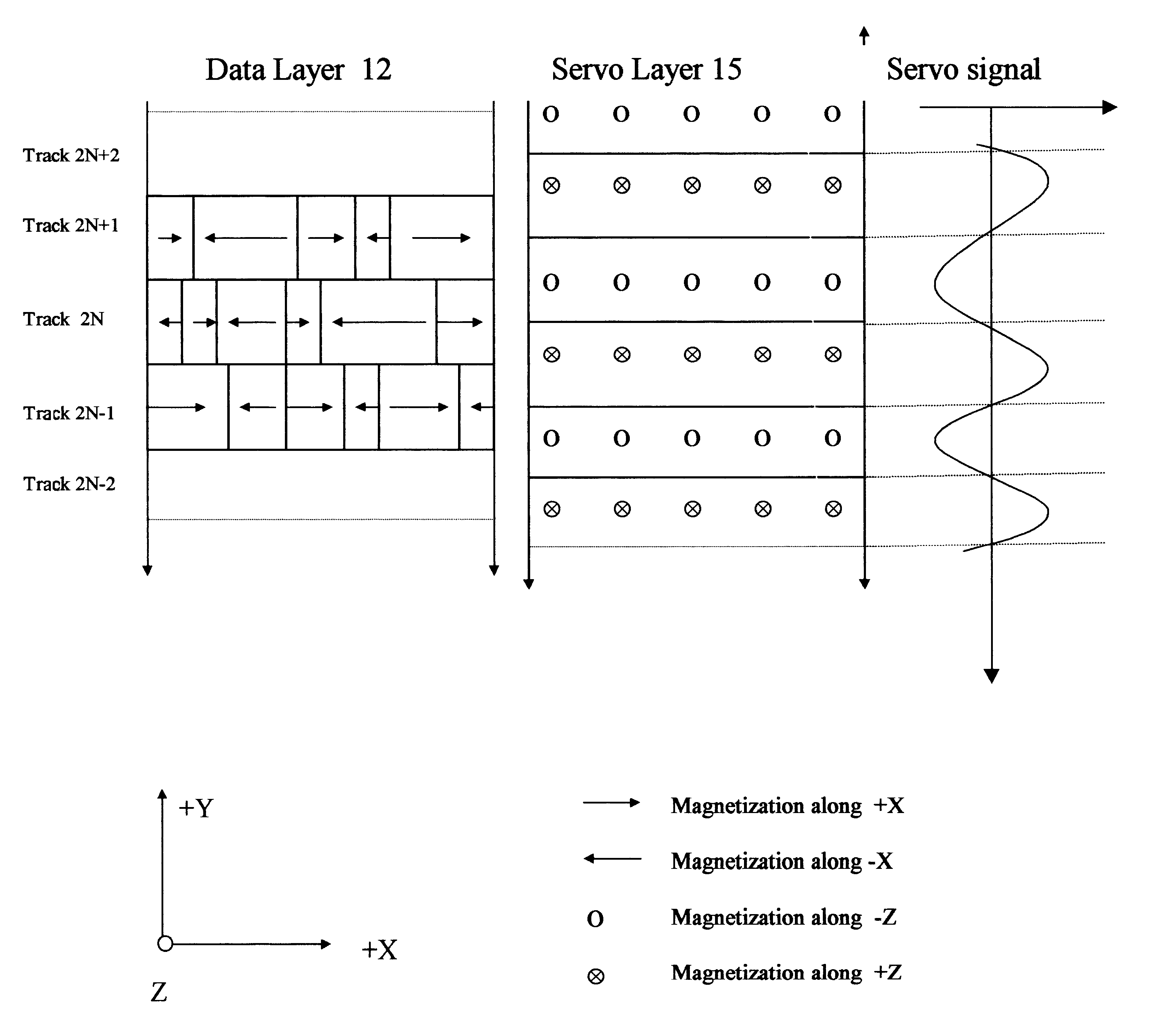
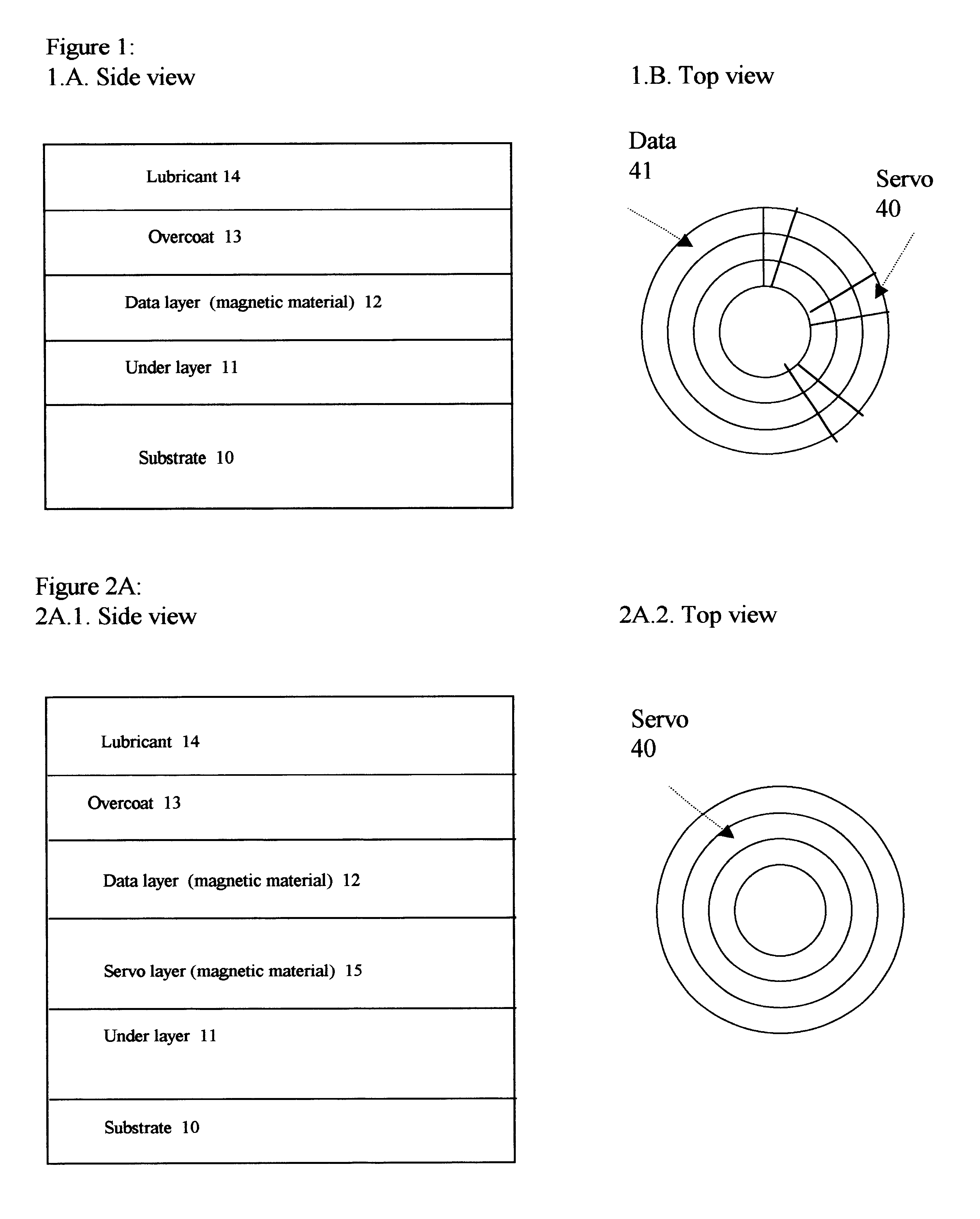
FIGS. 1A and B show the structure of the conventional magnetic disk in the side and top views, respectively. This structure contains a single magnetic layer 12 used to record both the customer data and the servo and gray-code information. The typical layers of the magnetic recording disk are substrate 10, underlayer 11, recording data layer 12, overcoat 13 and lubricant 14. As shown in FIG. 1B, the servo and gray code signals 40 are placed as radial wedges between the data zones 41. High track density requires more servo information; consequently, the space for the customer data is reduced.

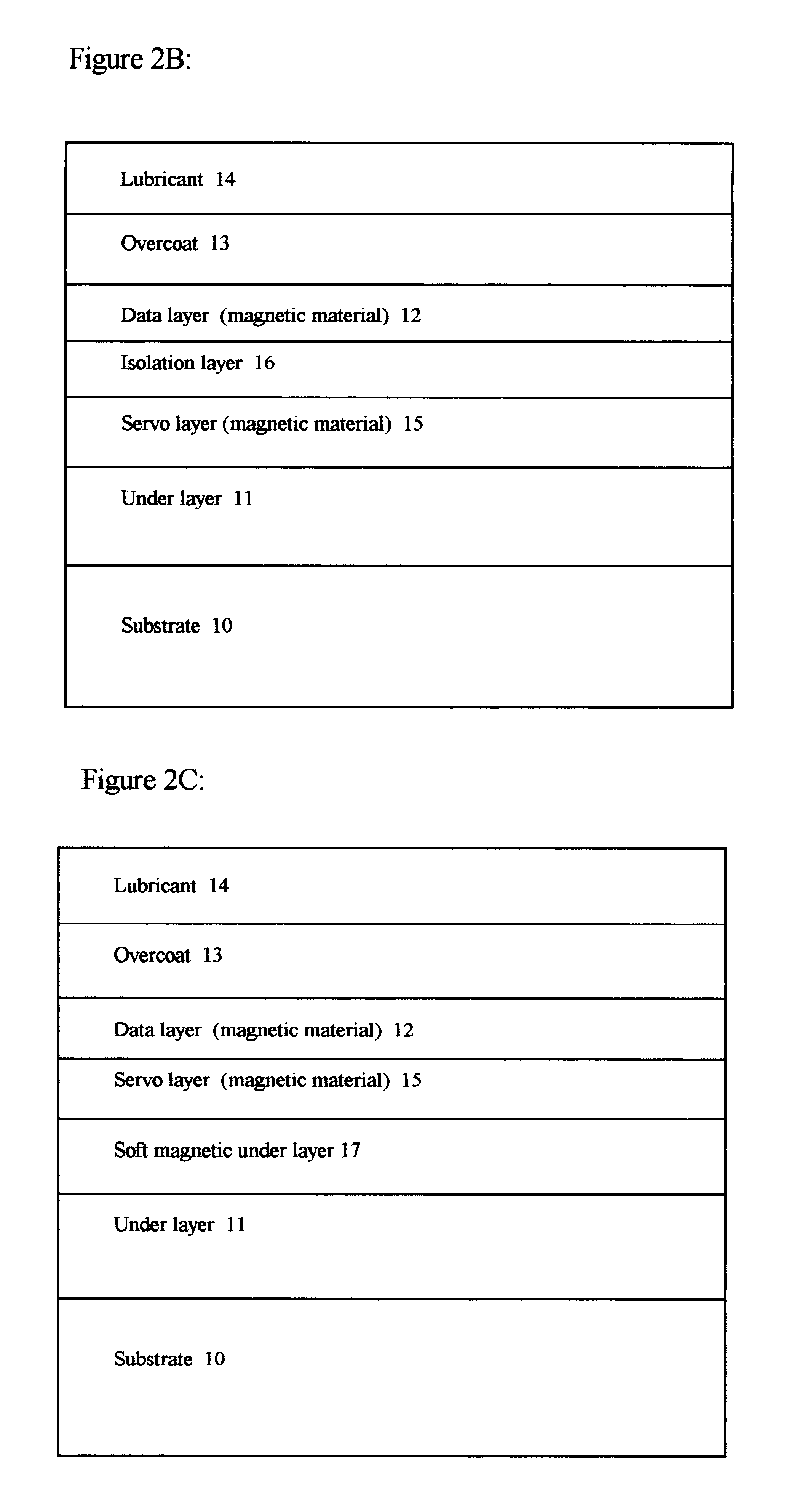
In this invention, we introduce the second magnetic layer 15 to generate the continuous servo signals. FIGS. 2A.1, 2B and 2C show the magnetic disks with two recordable magnetic layers, one for customer data (layer 12) and the other for servo (layer 15). FIG. 2A.2 shows the top view of the servo 40 over the fill recordable disk surface. In FIG. 2B, an extra layer 16 for magnetic isolation is inser...


PUM


Abstract

A magnetic recording system containing magnetic recording media with separate data and servo magnetic layers is disclosed. A servo magnetic layer resides usually below the data layer and has higher coercivity than that of the data layer. Interference between the data and servo signals is minimized by recording the servo patterns perpendicular or transverse direction with respect to the orientation of data bits. In addition, servo patterns are selected so that no interference with the data is generated by the servo pattern when the reader is in the middle of data tracks. Tracking error signals are approximately linear with track misregistration around the middle of data tracks. Finally, interference between the data and servo signals is further reduced by electronic processing. Continuous servo signals permit increased track densities with a single actuator and very high track densities with dual microactuator-actuator system.

Description

FIELD OF THE INVENTIONThe present invention is related to digital magnetic data storage and, in particular, to continuous magnetic servo systems.BACKGROUNDIn a disk-storage system, either magnetic or optical, the servo scheme plays an extremely important role. An efficient servo scheme will increase not only the data density but also the system performance, such as access time. In current magnetic recording technology, the sampled-servo scheme makes it impossible to achieve high track density; this is because the increasing sampling frequency leads to gains the track density but, at the same time, enlarges the overhead. With the present servo schemes, continuous servo does not leave any space for data.In contrast, in optical disk data storage, a continuous servo signal is obtained from the diffraction of the pre-grooved substrate. The track densities are many times higher than in magnetic hard disk drive (HDD). If the HDD could achieve the same track density as the optical drive, th...

Claims


Application Information

Patent Timeline
IPC IPC(8): G11B5/09G11B5/596
CPCG11B5/5965
Inventor HSIEH, YUNG-CHIEHNOVOTNY, VLAD
Owner HSIEH YUNG CHIEH
Why Eureka
Try Eureka