
Efficient waveguide arrays with nearly perfect element patterns

Inactive Publication Date: 2005-03-29
CALLAHAN CELLULAR L L C
View PDF10 Cites 22 Cited by
  • Summary
  • Abstract
  • Description
  • Claims
  • Application Information

AI Technical Summary

Benefits of technology

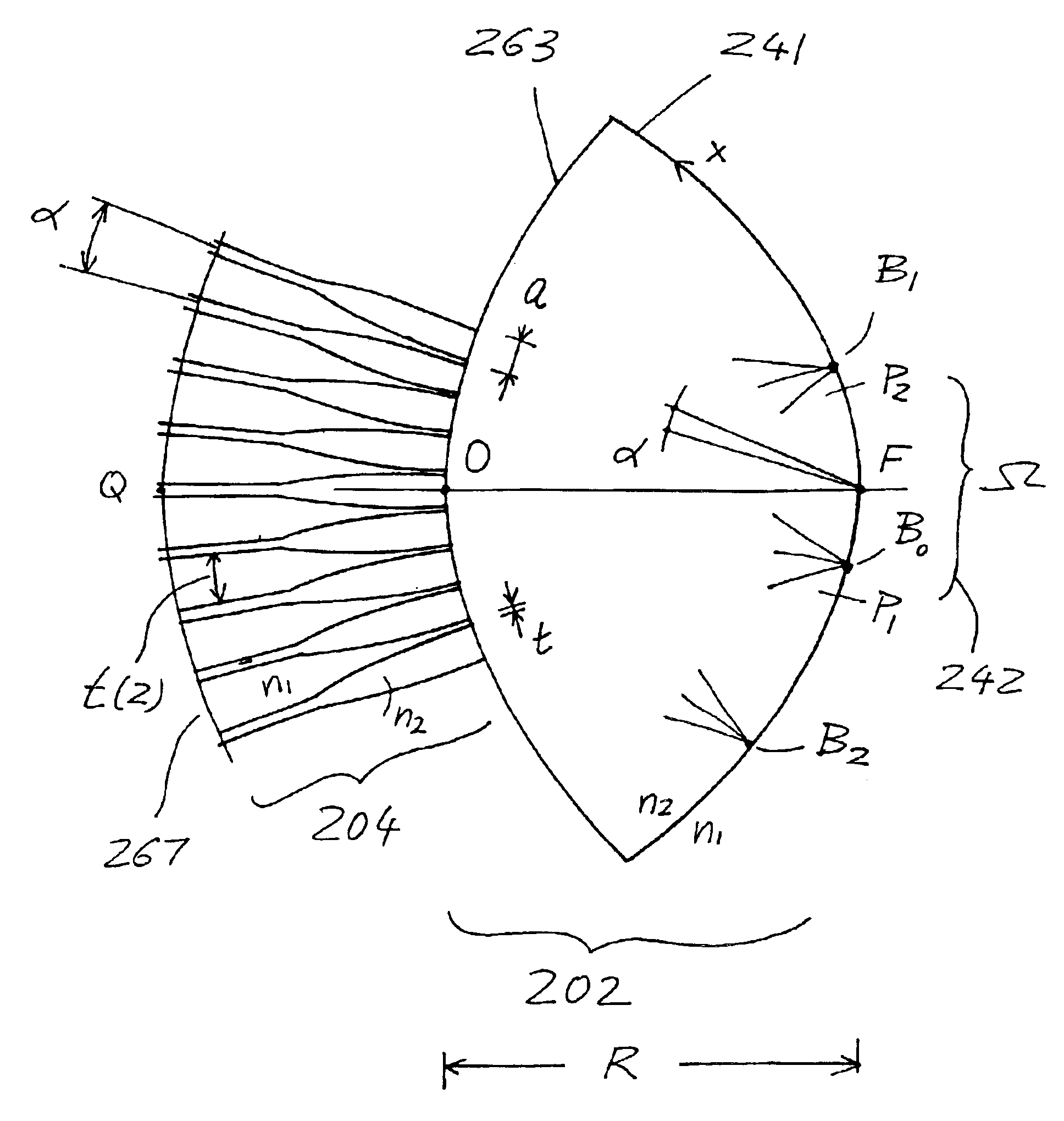
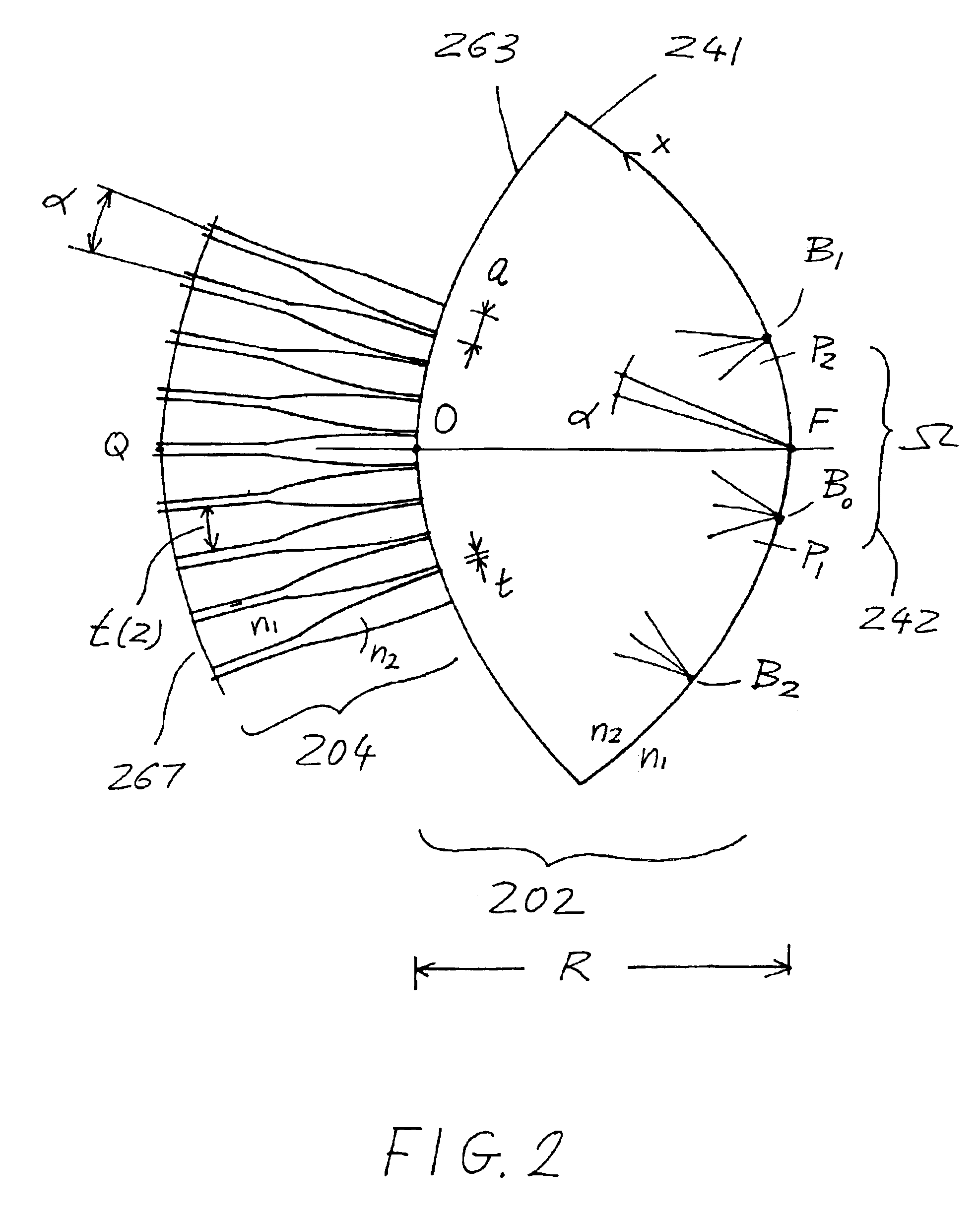
The present invention, efficient waveguide arrays with nearly perfect element patterns, provides essentially nearly ideal planar imaging by using waveguide arrays. An optical interconnection apparatus including waveguide arrays such as waveguide lenses, waveguide gratings and star couplers, has improved efficiency realized by using a periodic array including in each period a combination of two radial waveguides. The array is formed with angular period α between an input circle and an output circle and it includes an input section, connected to the input circle, and an output section connected to the output circle. The input section includes a single waveguide in each period and it is efficiently coupled with minimal loss to the output section, whose waveguides are approximately arranged with period α / 2 in the final region close to the output circle.

Problems solved by technology

Such losses seriously limit the usefulness of the router for passive networks and applications such as channel dropping filters with stringent requirements on loss uniformity.

Method used


Image

  • Efficient waveguide arrays with nearly perfect element patterns
  • Efficient waveguide arrays with nearly perfect element patterns
  • Efficient waveguide arrays with nearly perfect element patterns

Examples


Embodiment Construction

In the following description, identical element designations in different figures represent identical elements. Additionally in the element designations, the first digit generally refers to the figure in which that element is first located (e.g., 102 is first located in FIG. 1).

The present invention, efficient waveguide arrays with nearly perfect element patterns, provides the realization of nearly ideal planar imaging by using waveguide arrays. To this purpose, each array must be characterized to a good approximation by a rectangular element pattern. In one embodiment the array consists essentially of an adiabatic transition that is initially periodic with period α and it becomes periodic with period α / 2 at the end of the transition. The array element pattern in this case is almost exactly a rectangular pattern with negligible loss. However, a disadvantage of this array is that it requires a very long transition, which may be difficult to realize with sufficient accuracy. Therefore...


PUM


Abstract

An optical interconnection apparatus including waveguide arrays such as waveguide lenses, waveguide gratings and star couplers, has improved efficiency realized by using a periodic array including in each period a combination of two radial waveguides. The array is formed with angular period α between an input circle and an output circle and it includes an input section, connected to the input circle, and an output section connected to the output circle. The input section includes a single waveguide in each period and it is efficiently coupled with minimal loss to the output section, whose waveguides are approximately arranged with period α / 2 in the final region close to the output circle.

Description

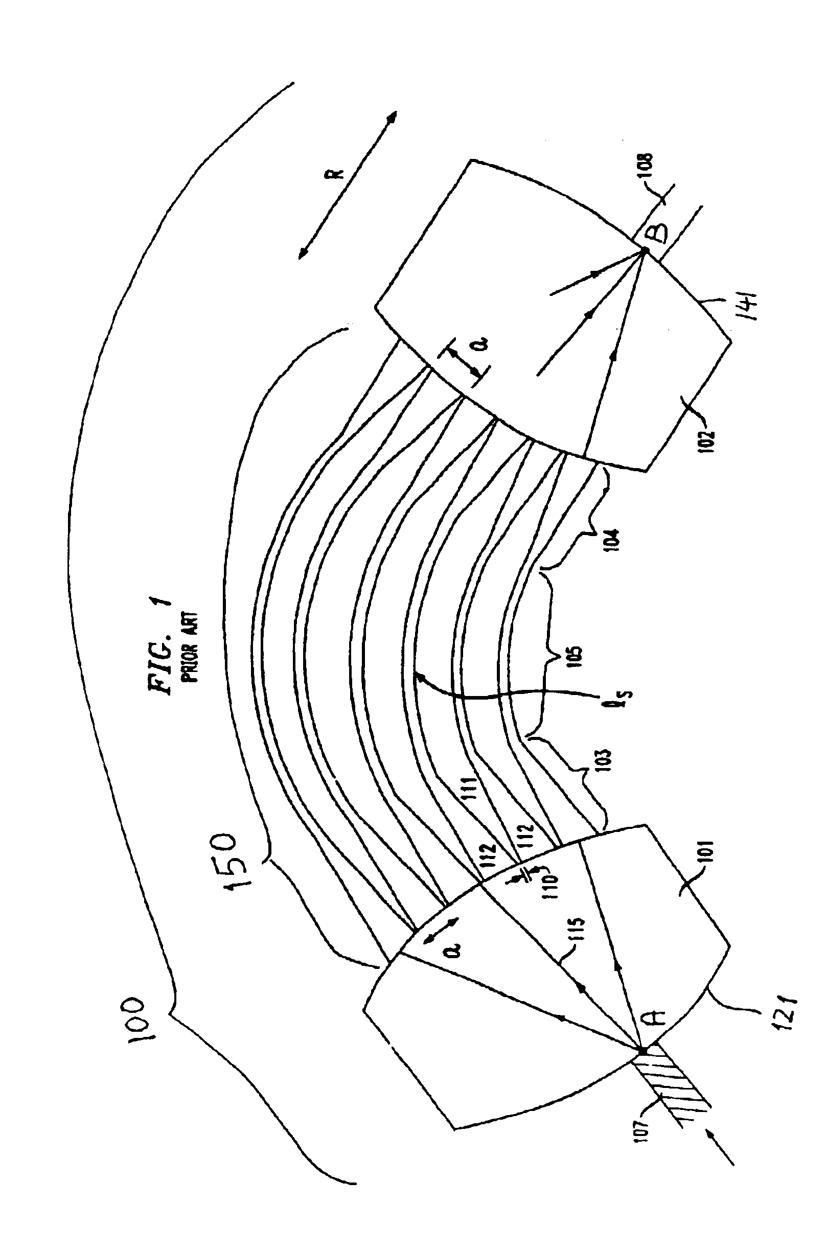
FIELD OF THE INVENTIONThis invention relates to waveguide arrays in optical and radio systems, and more particularly, to waveguide arrays having improved efficiency for wavelength routers and star couplers in integrated optics.BACKGROUND OF THE INVENTIONWaveguide arrays are used at radio and optical wavelengths. In particular they are used at optical wavelengths to realize imaging lenses and gratings in wavelength routers. One such wavelength grating router is described in U.S. Pat. No. 5,136,671, issued on Aug. 4, 1992. As shown in FIG. 1, this router is an imaging arrangement formed by a waveguide grating and it is generally composed of two dielectric slabs 101 and 102, two periodic arrays 103 and 104, and a set of waveguides (grating arms) 105, of different lengths between the two arrays. Typically, in commercial routers the loss exceeds 3 db for the central ports of the router and, for the marginal ports it often exceeds 6 db. Such losses seriously limit the usefulness of the ro...

Claims


Application Information

Patent Timeline
IPC IPC(8): G02B6/34
CPCG02B6/12011
Inventor DRAGONE, CORRADO P.
Owner CALLAHAN CELLULAR L L C
Learn More