System for monitoring mechanical waves from a moving machine

a mechanical wave and moving machine technology, applied in the direction of static/dynamic balance measurement, instruments, grain treatment, etc., can solve the problems of crude method, higher noise transmission, and only qualitative investigation of the state of the charge inside the mill, so as to reduce the number/amplitude/frequency, reduce the value of vibration, and reduce the number of operation speed.

Inactive Publication Date: 2005-04-05
COMMONWEALTH SCI & IND RES ORG
View PDF8 Cites 83 Cited by
  • Summary
  • Abstract
  • Description
  • Claims
  • Application Information

AI Technical Summary

Benefits of technology

It is preferred that the method includes producing a preferred operational speed for the machine in order to minimise the number / amplitude / frequency of vibrational events occurring within the machine for a particular value of θ.
Preferably the method of controlling operational parameters of a machine includes using a value of F for a particular amount of particulate matter within a machine in order to identify a preferred speed of operation of the machine whereby the number / amplitude / frequency of vibrational events occurring within the machine is minimised.
Minimsation of number / amplitude / frequency of vibrational events occurring within the machine can be produced by choosing an operational speed of the machine which minimises the value of f.
It is preferred that impact on the machine caused by the toe and shoulder of the particulate matter is able to be monitored in order to minimise wear and tear on the liner or other parts of the machine.

Problems solved by technology

However, the method is crude in that it uses sound intensity at only two fixed points outside the mill.
The technique therefore only permits qualitative investigation of the state of the charge inside the mill.
Low pulp density was thought to result in higher transmission of noise and increased media / media and media / liner collision events.

Method used


Image

  • System for monitoring mechanical waves from a moving machine
  • System for monitoring mechanical waves from a moving machine
  • System for monitoring mechanical waves from a moving machine

Examples


Embodiment Construction

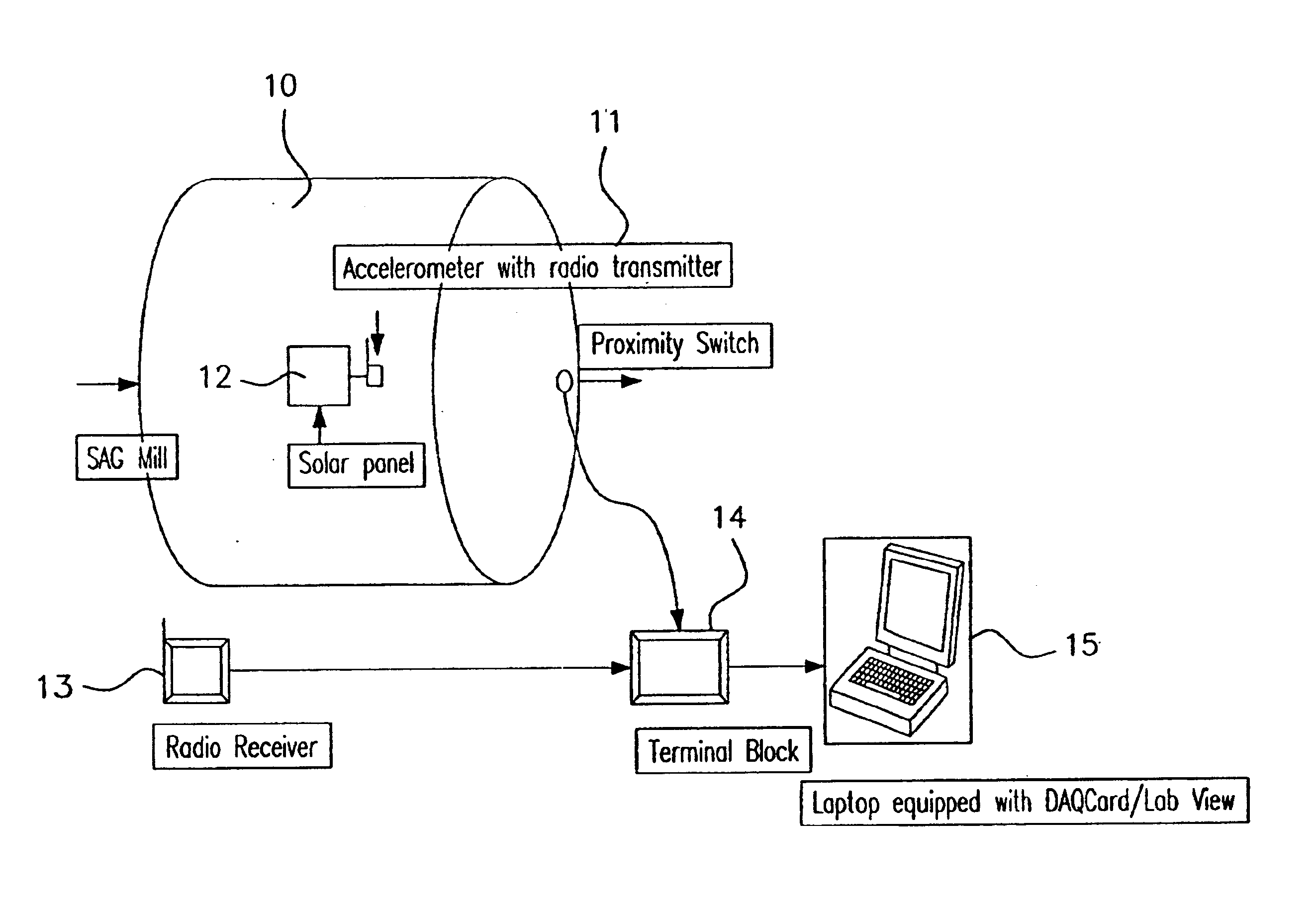
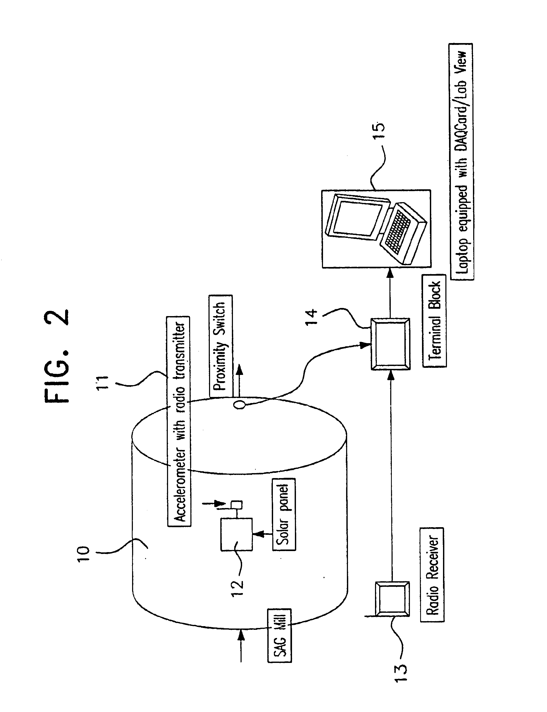
An example of a system for monitoring vibrational events occurring within an SAG 10 Mill will now be described.

An SAG Mill 10 consists of a metal cylindrical drum containing metallic ball bearings and particulate matter to be crushed.

The surface of the mill 10 is provided with an accelerometer 11 which is movably fixed thereto and includes a radio transmitter.

A solar panel 12 is electrically connected to the accelerometer 11 to provide a power supply.

A radio receiver 13 is connected to a stationery part of the SAG Mill framework and receives data transmitted by the radio transmitter of the accelerometer 11.

The radio receiver is hardwired to a terminal block 14 and a laptop computer 15 is able to be connected to the terminal block to receive data sensed by the accelerometer.

One or more proximity switches are located on the rotating part of the mill 10 to enable the position of the accelerometer to be located relative to the rate of rotation of the mill.

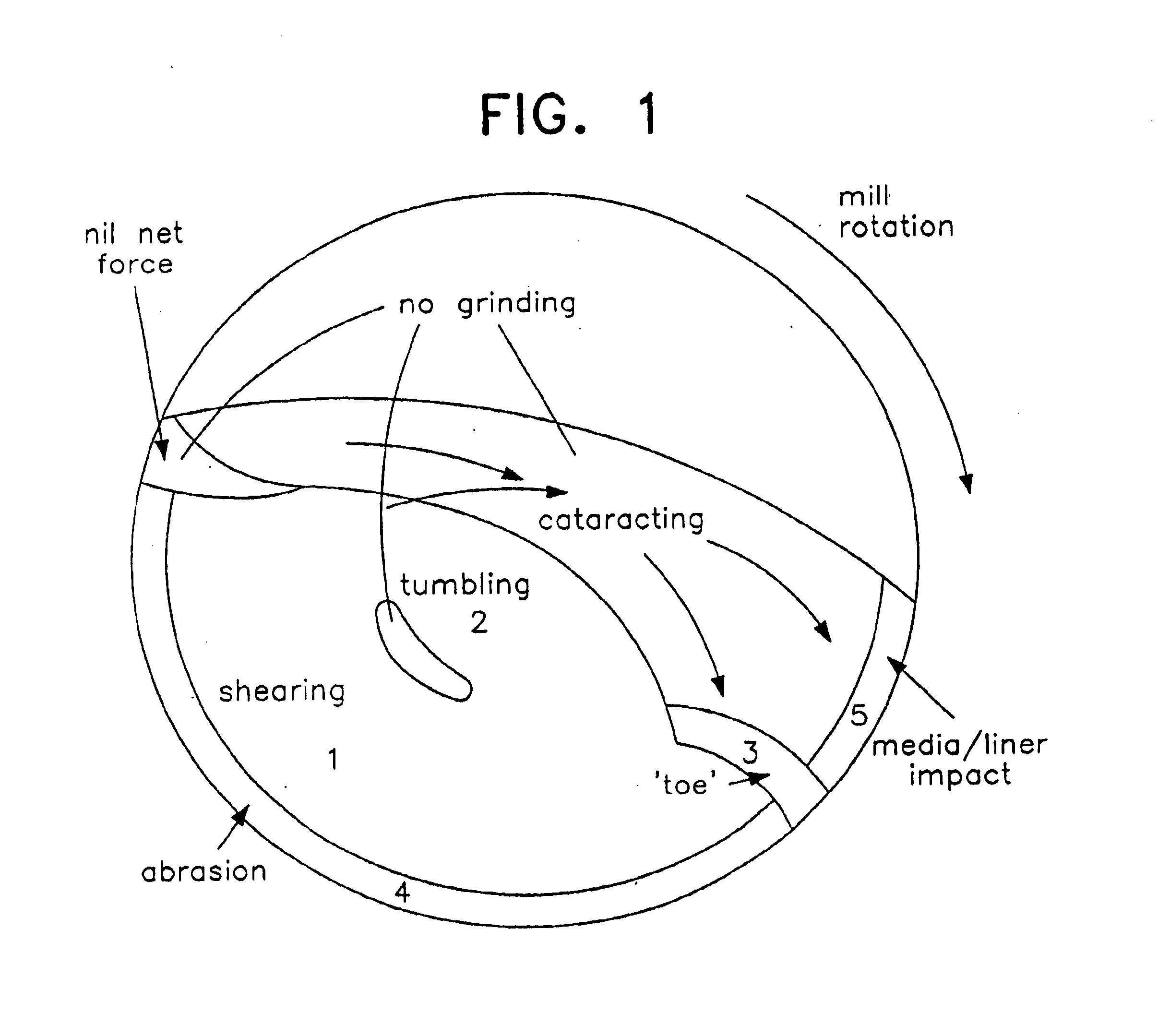
The operation of a SAG mill 10 ...


PUM

PropertyMeasurementUnit
frequencyaaaaaaaaaa
frequencyaaaaaaaaaa
frequencyaaaaaaaaaa

Abstract

A system for monitoring mechanical waves from a machine which in operation has moving particulate matter therein, the system including at least one sensor located on the machine at a location away from the central axis of the machine, the sensors being for sensing acoustic waves and including a transmitter for transmitting signals representing the sensed mechanical waves to a receiver at a location remote from the sensor(s), a data processor connected to the receiver for receiving signals from the receiver which signals represent the mechanical waves and processing the signals to produce output signals for display on a display means, wherein the output signals for display represent one or more parameters indicative of mechanical waves emitted from the machine over a predetermined period of time.

Description

FIELD OF THE INVENTIONThis invention relates to the monitoring and analysis of surface vibration waves generated by the operation of material processing equipment. ‘The invention is of particular application to the non-intrusive monitoring and control of mineral processing equipment, such as tumbling mills, where the equipment component being monitored is in motion. The invention also has application to equipment with stationary components but moving mineral particles or pulp flows, such as crushers and hydrocyclones. The invention was initially developed for condition monitoring and process control of Semi-Autogenous Grinding (SAG) mills.BACKGROUND OF THE INVENTIONAcoustic emissions and surface vibrations monitoring, have previously been used to investigate and control the performance of mineral processing unit operations. Control of power draft in autogenous grinding (AG) mills and SAG mills has traditionally been via load cells estimating the charge mass. However, acoustic emissi...

Claims


Application Information

Patent Timeline
Patent Type & Authority Patents(United States)
IPC IPC(8): B02C17/00B02C17/18B02C25/00G01H1/00G01H3/12G01N29/04G01N29/06G01N29/14G01N29/46
CPCB02C17/1805G01H1/003G01H3/12G01N29/46G01N29/0609G01N29/14G01N29/449G01N29/046B02C25/00
Inventor CAMPBELL, JONATHAN JOSEPHLIU, YISHARP, VICTORSPENCER, STEVEN JOHNWELLER, KEITH RUSSELL
Owner COMMONWEALTH SCI & IND RES ORG
Why Eureka
Try Eureka