
Mounting cylinder for mounting cylindrical embossing tools for embossing rolls

a technology for mounting cylinders and embossing tools, which is applied in the direction of printing, rotary presses, decorative arts, etc., can solve the problems of unsuitable mounting cylinders from printing technology for embossing diffraction gratings and holograms, inconvenient reset, and high cost, and achieves the effect of convenient res

Inactive Publication Date: 2005-04-05
GIESECKE & DEVRIENT GMBH
View PDF9 Cites 22 Cited by
  • Summary
  • Abstract
  • Description
  • Claims
  • Application Information

AI Technical Summary

Benefits of technology

It is the problem of the present invention to propose a simply constructed mounting cylinder that can be tempered from inside, on the one hand, and is easy to reset from one embossing tool to another embossing tool, in particular with different diameters, on the other hand, as well as a method for mounting cylindrical embossing tools.
Integration of the compressed air pipes into the mounting shell of the mounting cylinder substantially facilitates replacement of the mounting shell. In particular, it is unnecessary to replace the whole mounting cylinder when a mounting shell with a greater outside diameter is merely to be used for mounting a embossing tool of greater diameter. The driveshaft and the fixing device for fixing the mounting shell coaxially with the driveshaft can be retained.
However, flow through the mounting shell itself instead of through a hollow space formed between the mounting shell and the shaft offers different advantages. Firstly, the tempering of the outer mounting shell surface is only negligibly dependent on the thickness of the mounting shell. That is, upon a format change from a cylindrical embossing tool (sleeve) with a comparatively small diameter to a embossing tool with a comparatively great diameter, it is merely necessary to replace a thin-walled mounting shell with an accordingly thicker-walled mounting shell, without this having an essential effect on the tempering of the mounting shell surface. Furthermore, the structure of the shaft is substantially less complicated, which has a positive effect on the production cost and stability of the shaft. In addition, it is unnecessary to empty tempering fluid from the system before changing one mounting shell for another mounting shell, since the system is hermetically sealed assuming the use of suitable, in particular self-closing, valves. Finally, integration of the tempering device into the mounting shell offers sealing advantages, since it is merely necessary to seal the feed and discharge connections, which is no problem using suitable valves. It is substantially more troublesome, in contrast, to seal the hollow space between the shaft and the mounting shell for receiving tempering fluid.
The mounting shell is preferably made of aluminum or an aluminum alloy. Aluminum combines some essential material properties, having a high coefficient of thermal conduction, on the one hand. Aluminum is comparatively elastic, on the other hand, permitting the mounting shell to be expanded elastically without great effort for tightly clamping the mounted sleeve. Furthermore, aluminum can be easily machined due to its low strength, so that the outside diameter of the mounting shell can be precisely adjusted in simple fashion by truing the outer surface.

Problems solved by technology

However, the printing forms used here that are mounted on the mounting cylinder are thick-walled and very massive, so that the mounting cylinder is accordingly adapted mechanically due to the high clamping powers occurring during mounting.
Mounting cylinders from printing technology are therefore unsuitable for embossing diffraction gratings and holograms, since the embossing tools used for embossing, which are usually made of nickel, exist as tubular, thin-walled so-called sleeves with a wall thickness of only a few tenths of a millimeter.
In the case of heat curing lacquers, however, the supply of heat can be required.
However, the above-described mounting cylinder is of extremely complex structure.
This is not only cost-intensive but also time-consuming, since it is in each case necessary to completely remove the shaft axle, thereby also separating the shaft axle from the connections for compressed air and tempering medium.

Method used


Image

  • Mounting cylinder for mounting cylindrical embossing tools for embossing rolls
  • Mounting cylinder for mounting cylindrical embossing tools for embossing rolls
  • Mounting cylinder for mounting cylindrical embossing tools for embossing rolls

Examples


Embodiment Construction

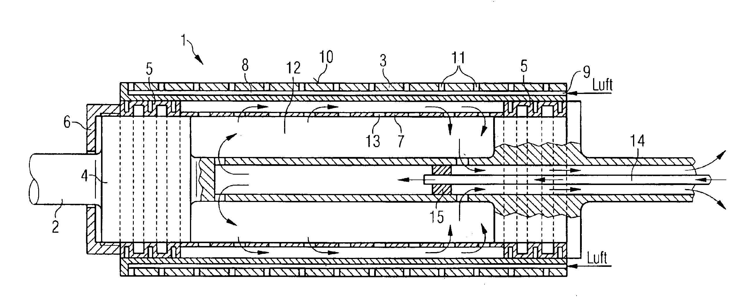
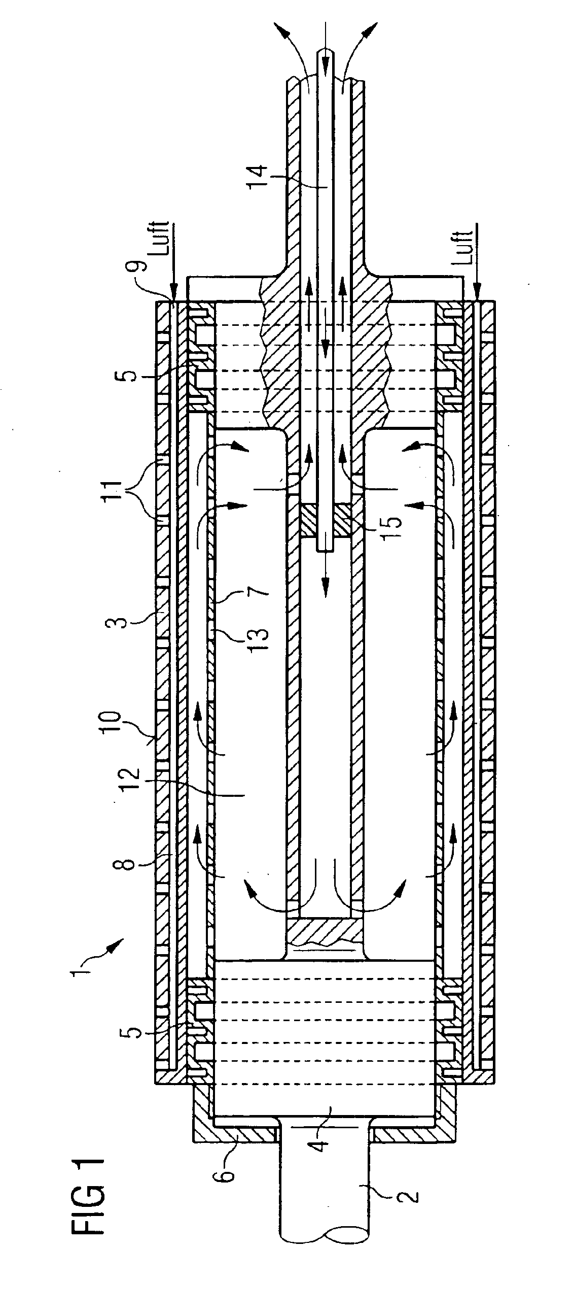
FIG. 1 shows a mounting cylinder according to a first embodiment of the first variant of the invention. The representation in FIG. 1 only shows the construction schematically, omitting components irrelevant to the invention. Mounting cylinder 1 comprises driveshaft 2 and mounting shell 3 mounted by fixing devices 5 on two shaft shoulders 4 of wider diameter.

Fixing device 5 is executed as a pressure sleeve here and works according to the principle that axial compression of the pressure sleeve causes radial expansion thereof. The axial compression force is applied to pressure sleeve 5 shown on the left in FIG. 1 by means of schematically shown adjusting nut 6, and transferred to pressure sleeve 5 disposed on the opposite end of the shaft by means of spacer tube 7, so that both pressure sleeves 5 are compressed axially and thus expanded radially to the same extent by adjusting nut 6. Mounting shell 3 can thus be slipped onto pressure sleeves 5 with or without a mounted sleeve, and clam...


PUM


Abstract

A mounting cylinder (1) for mounting cylindrical embossing tools for embossing rolls for embossing diffraction gratings or holograms includes a mounting shell (3) for mounting the embossing tool and a fixing device for fixing the mounting shell (3) on a shaft (2) and a tempering device for tempering the mounting shell. According to one variant, the embossing tool is expanded by compressed air in order to be slipped onto the mounting shell or removed therefrom, a compressed air channel system (8) with radial compressed air discharge openings (11) extending axially and / or tangentially within the mounting shell (3). According to another variant, the mounting shell is expanded mechanically in order to fix a embossing tool slipped over the mounting shell and simultaneously fix the mounting shell (3) on the shaft (2).

Description

BACKGROUND OF THE INVENTION1. Field of the InventionThe present invention relates to field of mounting cylindrical embossing tools for embossing rolls.2. Description of the Background ArtThis invention relates to a mounting cylinder and a method for mounting cylindrical embossing tools for embossing rolls, in particular for embossing diffraction gratings or holograms on plastic foils and other substrates. Such embossing tools have a partially or completely structured surface which, after the embossing tool has been mounted on the mounting cylinder, is molded into an embossing lacquer by the endless rotary method. Because the lacquer layer into which embossing is done is relatively thin, it is preferable to use “endless” embossing tools that do not have either an abutting edge or butt joint or a bulky seam.Mounting cylinders for similar purposes are known from printing technology. However, the printing forms used here that are mounted on the mounting cylinder are thick-walled and ver...

Claims


Application Information

Patent Timeline
IPC IPC(8): B41F13/22B41F13/08B41F27/00B41F27/10
CPCB41F13/22B41F27/105B44B5/0009F28F5/02B41P2227/21
Inventor HOFFMANN, LARSPRETSCH, ANDREASRADLER, ANDREAS
Owner GIESECKE & DEVRIENT GMBH
Learn More