
Driving apparatus for speed changing and steering of a vehicle

Inactive Publication Date: 2005-04-05
TUFF TORQ
View PDF148 Cites 25 Cited by
  • Summary
  • Abstract
  • Description
  • Claims
  • Application Information

AI Technical Summary

Benefits of technology

A first object of the present invention is to provide a compact, low production cost driving apparatus for speed changing and steering of a vehicle including a pair of similarly structured driving units, each of which comprises a housing, an HST, a differential gear unit drivingly connected with the HST, and a pair of differential output shafts, enabling a vehicle provided with the driving apparatus to be operated in a straight line without requiring adjustment to equalize the output of both driving units and to have a small turning radius.
Furthermore, a mower unit is provided to the vehicle with a driving apparatus of the present invention. The vehicle can spin or turn at a small radius beside or among trees or buildings, thereby enabling the lawn mowing to be performed efficiently.

Problems solved by technology

For example, if there is a difference in volume between hydraulic pumps or motors of the pair of the HSTs, feelings both in turning left and right are different from each other, thus the vehicle becomes hard to control.
This results in complicated linkages between the speed changing operating tool and the both output regulating members, and between the steering operating tool and the both output regulating members.
Thus, the cost for production of the linkages and the space required for them in the vehicle are increased.
These linkages also require a more complicated control system for a steering wheel and a speed changing pedal.
These vehicles, however, have a large turning radius which is inefficient when operating in crowded areas.
For example, when mowing lawn near trees, steered front wheels are inefficient because it takes several passes in order to complete the area adjacent to a single tree.

Method used


Image

  • Driving apparatus for speed changing and steering of a vehicle
  • Driving apparatus for speed changing and steering of a vehicle
  • Driving apparatus for speed changing and steering of a vehicle

Examples


Embodiment Construction

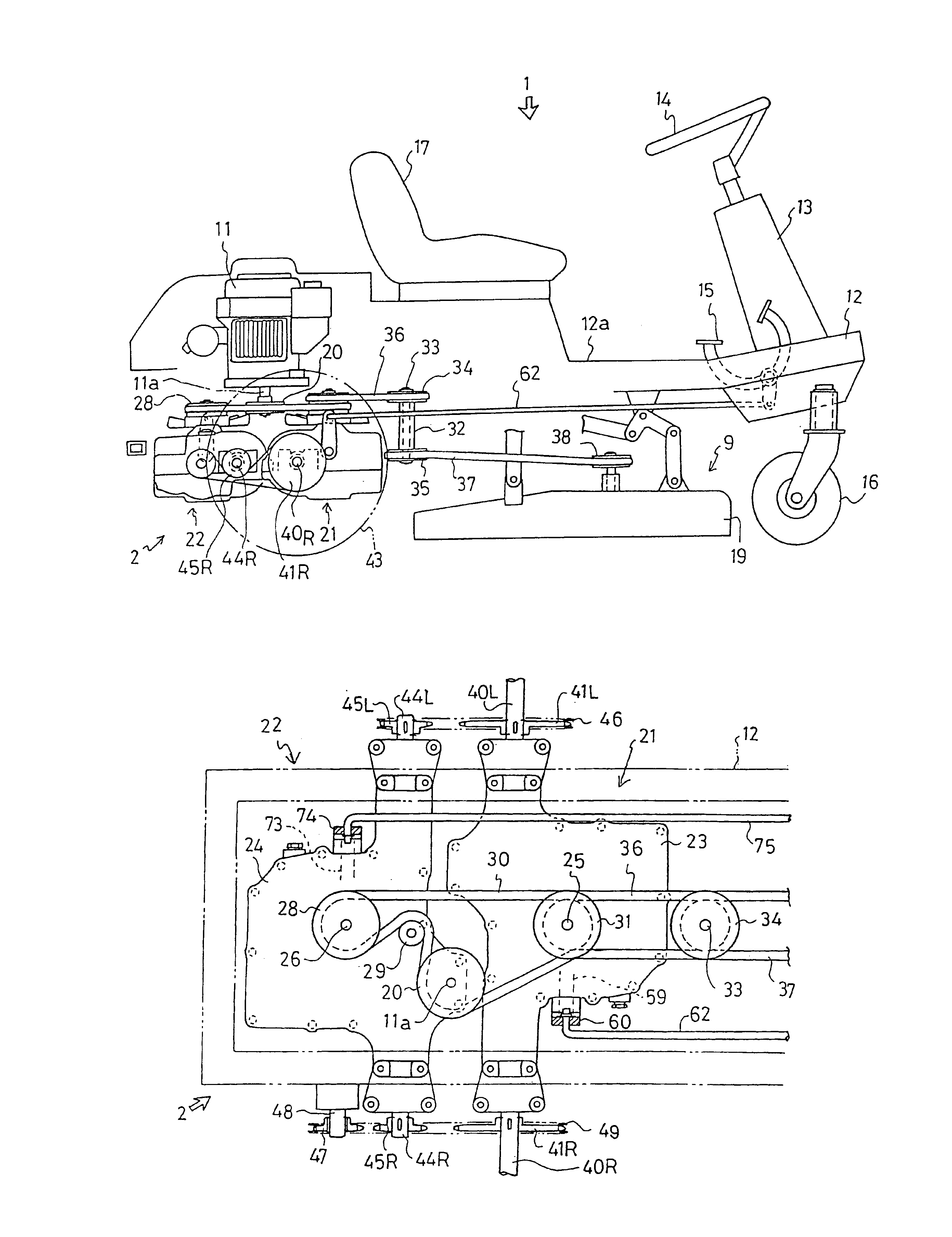
As best seen in FIG. 1, the overall construction of a lawn tractor 1 provided with a driving apparatus of the present invention will be explained.

A front column 13 is provided upright on a front portion of a vehicle chassis 12. A steering wheel 14 as a steering operating tool projects upwardly from front column 13. A speed change pedal 15 and brake pedals (not shown) are disposed beside front column 13. A pair of front wheels 16 are disposed respectively on both lateral sides of the front lower portion of vehicle chassis 12. Front wheels 16 are caster wheels, having substantially vertical pivots, so that they can be horizontally rotated smoothly so as to be rapidly oriented toward the aiming direction when the vehicle turns by differential driving of left and right driving wheels. Thus, the feeling in steering of the vehicle can be improved. A single front wheel 16 or more than two front wheels 16 may be also used.

A seat 17 is mounted on a center portion of vehicle chassis 12. A dec...


PUM


Abstract

A driving apparatus for speed changing and steering of a vehicle consists of a first driving unit for speed changing in advancing and reversing and a second driving unit for steering, which are arranged in a longitudinal row and are attached to a vehicle chassis. Each of the first driving unit and the second driving unit has a common structure, which comprises a housing and an HST and left and right differential output shafts contained in the housing. A left first differential output shaft and a left second differential output shaft are connected with each other so as to be rotated in the same direction, and a right first differential output shaft and a right second differential output shaft are connected with each other so as to be rotated in opposite directions. Both first and second HSTs of the first driving unit and a second driving unit receives power from engine through a common single belt. A movable swash plate of a hydraulic pump of the first HST is connected to a speed change pedal and a movable swash plate of a hydraulic pump of the second HST is connected to a steering wheel.

Description

BACKGROUND OF THE INVENTIONContinuation of U.S. application Ser. No. 09 / 837,419 filed Apr. 19, 2001, now U.S. Pat. No. 6,648,094 which is a continuation of U.S. application Ser. No. 09 / 700,147 filed Nov. 13, 2000, now U.S. Pat. No. 6,629,577.FIELD OF THE INVENTIONThe present invention relates to a driving apparatus for speed changing and steering of a vehicle comprising a pair of hydrostatic transmissions (hereinafter referred to as HSTs) for driving a pair of left and right axles, wherein one of the pair is used for steering and the other is used for speed changing in advancing and reversing.BACKGROUND ARTU.S. Pat. No. 4,782,650, for example, describes a vehicle provided with a pair of HSTs, which are disposed in a lateral row and are connected with each other, and left and right axles projecting respectively from the pair of the HSTs laterally outwardly. Driving wheels are fixed respectively onto utmost ends of the axles. The left and right axles are driven respectively by changin...

Claims


Application Information

Patent Timeline
IPC IPC(8): B60K17/10B62D11/18B62D11/06
CPCB60K17/105B62D11/18B60Y2200/223
Inventor ABEND, ROBERTSTOLL, KERWYN
Owner TUFF TORQ
Features
  • Generate Ideas
  • Intellectual Property
  • Life Sciences
  • Materials
  • Tech Scout
  • Unparalleled Data Quality
  • Higher Quality Content
  • 60% Fewer Hallucinations
Learn More