
Adjustable sprinkler riser with offset joint

a riser and sprinkler technology, applied in the field of sprinkler risers, can solve the problems of inability to easily adjust the height of the sprinkler riser, user's considerable time to reinstall a new, and the riser cannot be easily adjusted. , to achieve the effect of simple manufacturing process, less manufacturing cost and more durabl

Active Publication Date: 2005-04-05
HUSQVARNA AB
View PDF14 Cites 34 Cited by
  • Summary
  • Abstract
  • Description
  • Claims
  • Application Information

AI Technical Summary

Benefits of technology

The apparatus and method of the present invention have been developed in response to the present state of the art, and in particular, in response to problems and needs in the art that have not yet been fully resolved by currently available sprinkler risers. More specifically, the adjustable sprinkler riser is more durable than conventional adjustable sprinkler risers. The adjustable sprinkler riser also involves a simple manufacturing process and thus is less expensive to manufacture than conventional adjustable sprinkler risers.
The pinching seal may include a separate O-ring and pinching member or, alternatively, may be an integrated piece. The O-ring may have a round cross sectional shape and may be made from rubber. The O-ring is designed to be pressed at least partially into an opening formed where the inner telescoping member protrudes from the first interior channel of the outer telescoping member. Accordingly, the O-ring limits fluid leakage from the opening.
It is advantageous to offset the area of vulnerability to breakage of the inner telescoping member from the exposed segment of the second joint member. To be more particular, when the second joint member is secured to the first joint member such that the position of the inner telescoping member relative to the outer telescoping member is secured, the exposed segment of the second joint member is offset from the proximal end of the outer telescoping member. In certain embodiments, an offset between the engagement end of the first joint member and exposed segment is at least an eighth or a quarter of an inch.
The adjustable sprinkler riser involves a simple manufacturing process. The protrusion is formed on the outer telescoping member. The protrusion may be a ridge integrally formed with the outer telescoping member. Alternatively, the protrusion may be formed by placing an open-ended ring in a recess defined by the outer surface of the outer telescoping member.
In view of the foregoing, the adjustable sprinkler riser provides substantial advantages over conventional risers. When a position of the inner telescoping member relative to the outer telescoping member is secured, areas of vulnerability to breakage in the joint members and inner telescoping member are offset from each other to provide greater strength to the adjustable sprinkler riser. Also, the adjustable sprinkler riser involves a simple manufacturing process and is thus less expensive to manufacture than conventional adjustable risers.

Problems solved by technology

Unfortunately, conventional sprinkler risers suffer from at least one key limitation: the height of the sprinkler riser cannot be easily adjusted.
For instance, if the sprinkler riser emits water over a bush and the bush grows such that the bush obstructs the path of the emitted water, the user is required to expend a considerable amount of time to reinstall a new elongated section in order to project the water over the bush.
Unfortunately, these conventional adjustable risers also suffer from a number of key disadvantages.
First, conventional adjustable sprinkler risers are often fragile and can easily break.
This is because a joint between its extensible members is often not strong enough to withstand the forces that may be applied to it.
Furthermore, until the sprinkler riser is repaired, the associated sprinkler station, or even the entire sprinkler system, can become nonfunctional.
Second, manufacturing of conventional adjustable sprinkler risers is often relatively complex and thus inordinately expensive.
Competition in the sprinkler industry is fierce and profit margins are slim.

Method used


Image

  • Adjustable sprinkler riser with offset joint
  • Adjustable sprinkler riser with offset joint
  • Adjustable sprinkler riser with offset joint

Examples


Embodiment Construction

The preferred embodiments of the invention are now described with reference to FIGS. 1–4, wherein like parts are designated by like numerals throughout. The members of the present invention, as generally described and illustrated in the Figures, may be designed in a wide variety of configurations. Thus, the following more detailed description of the embodiments of the present invention, as represented in the Figures, is not intended to limit the scope of the invention, as claimed, but is merely representative of presently preferred embodiments of the invention.

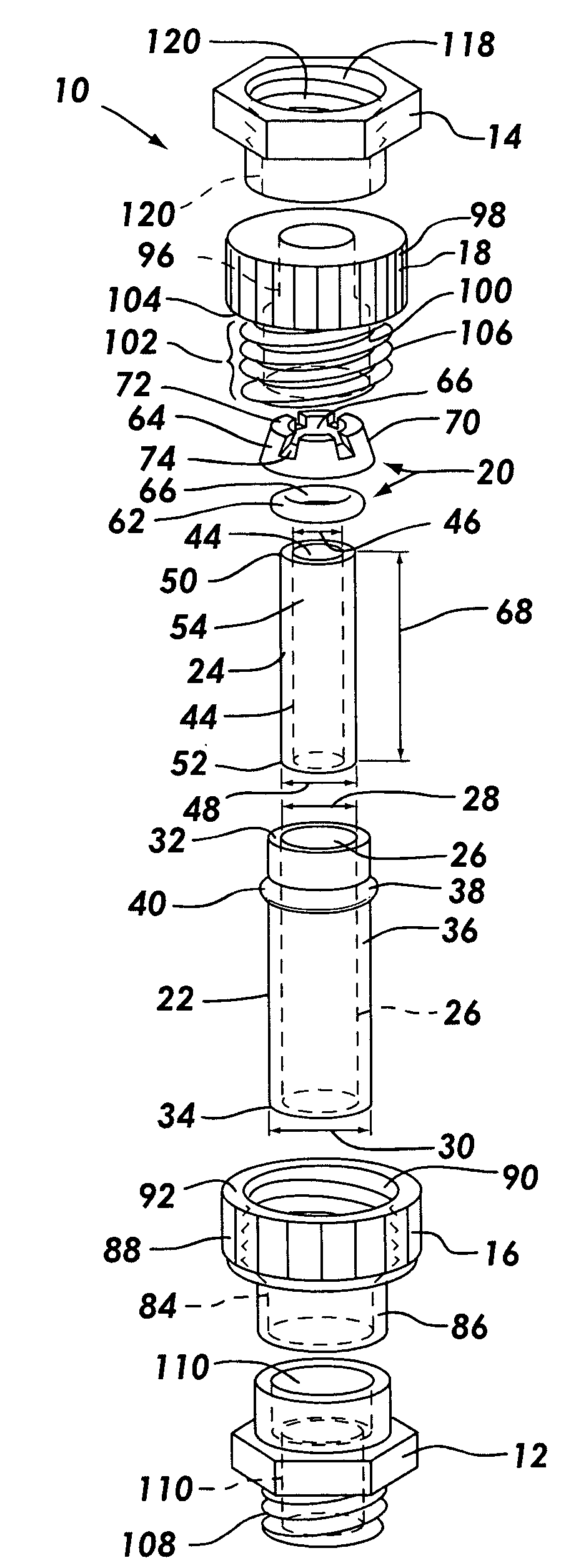
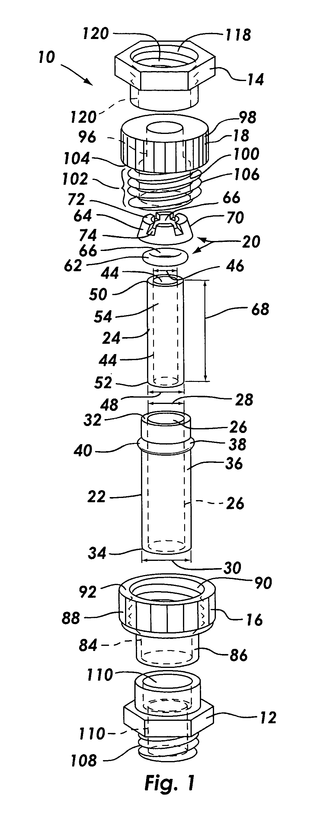
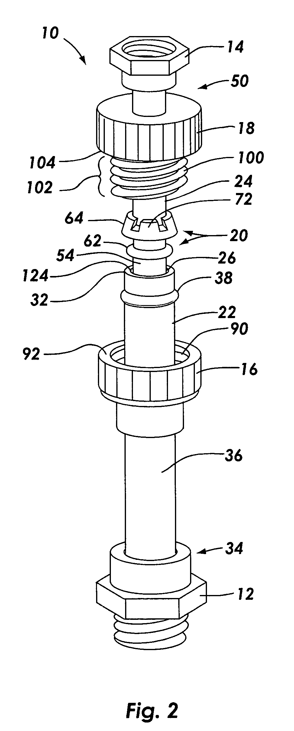
With reference to FIG. 1, there is shown an exploded view of the adjustable sprinkler riser 10. In overview, the adjustable sprinkler riser 10 includes a first threaded interface 12, a second threaded interface 14, a first joint member 16, a second joint member 18, a pinching seal 20, an outer telescoping member 22, and an inner telescoping member 24. Each of these components and its function in the adjustable sprinkler riser...


PUM


Abstract

The adjustable sprinkler riser includes an outer and an inner telescoping member that telescopically interface with each other. A protrusion is spaced from a proximal end of the outer telescoping member. A first joint member slidably interfaces with the outer telescoping member, and a second joint member slidably interfaces with the inner telescoping member. The second joint member may be selectively secured to the first joint member to restrict movement of the inner telescoping member relative to the outer telescoping member. In such a condition, areas of vulnerability to breakage in the joint members and inner telescoping member are offset from each other to provide greater strength to the adjustable sprinkler riser. In addition, manufacturing the adjustable sprinkler riser is simple because the first and second joint members may be conveniently placed on the telescoping members, and there is no need to form threads or other intricate structures on the telescoping members.

Description

1. Field of the Invention The present invention relates to a sprinkler riser. More specifically, this invention relates to an adjustable sprinkler riser. 2. Description of Related Art A conventional sprinkler riser includes a first attachment mechanism for attaching the riser to a sprinkler system, an intermediary elongated section, and a second attachment mechanism for attaching the riser to a sprinkler head. Conventional sprinkler risers provide substantial advantages to their users. With a sprinkler riser, certain areas of a lawn or garden may be watered without repositioning underground piping. Furthermore, a stream of water may be emitted over a wall, bush, small tree, or shrubbery to a desired location. Unfortunately, conventional sprinkler risers suffer from at least one key limitation: the height of the sprinkler riser cannot be easily adjusted. For instance, if the sprinkler riser emits water over a bush and the bush grows such that the bush obstructs the path of the emitte...

Claims


Application Information

Patent Timeline
IPC IPC(8): B05B15/00B05B15/06F16L19/00F16L19/12
CPCF16L19/12B05B15/068B05B15/656
Inventor ERICKSEN, KENT C.MADSON, CRAIG J.
Owner HUSQVARNA AB
Learn More