
Light source device

a light source and light source technology, applied in the direction of mechanical equipment, lighting and heating equipment, instruments, etc., can solve the problems of excessive narrow distribution, complicated molding process, and wide distribution, and achieve the effect of enhancing the efficiency of the light amount of the primary light source, enhancing the light amount, and very high luminan

Inactive Publication Date: 2005-04-05
MITSUBISHI RAYON CO LTD
View PDF12 Cites 41 Cited by
  • Summary
  • Abstract
  • Description
  • Claims
  • Application Information

AI Technical Summary

Benefits of technology

"The present invention provides a light source device with improved control over emitted light, increased efficiency of the primary light source, and enhanced image quality with a simple construction. The device includes a primary light source, a light guide, and a light deflecting device. The light deflecting device has elongated prisms with a light incident surface and a light emission surface. The elongated prisms have a convex surface shape with a maximum distance from the primary light source, and the peak emission light is internally totally reflected and emitted in a desired direction. The ratio of the maximum distance between the convex surface shape of the elongated prisms and the virtual prisms is equal to 0.2 to 2%. The light source device also has a light emission face with a directed light emission function. The invention also provides a method for designing the light source device."

Problems solved by technology

Therefore, the molding process is complicated.
However, the prism faces of convex surface shape described in the above patent publications are relatively too large or too small in the radius of curvature, and therefore it is not sufficient to narrow the distribution of light emitted from the light guide, or it excessively narrow the distribution or often broaden the distribution.
In addition, with respect to the light guides described in the above patent publications, they have light emission function which achieve not so high directivity in the emitted light distribution and therefore the emitted light becomes to have relatively broad distribution, so that the sufficient enhancement in luminance cannot be achieved even if the light emitted from the light guide is concentrated with use of the prism sheet.

Method used


Image

  • Light source device
  • Light source device
  • Light source device

Examples


example 1

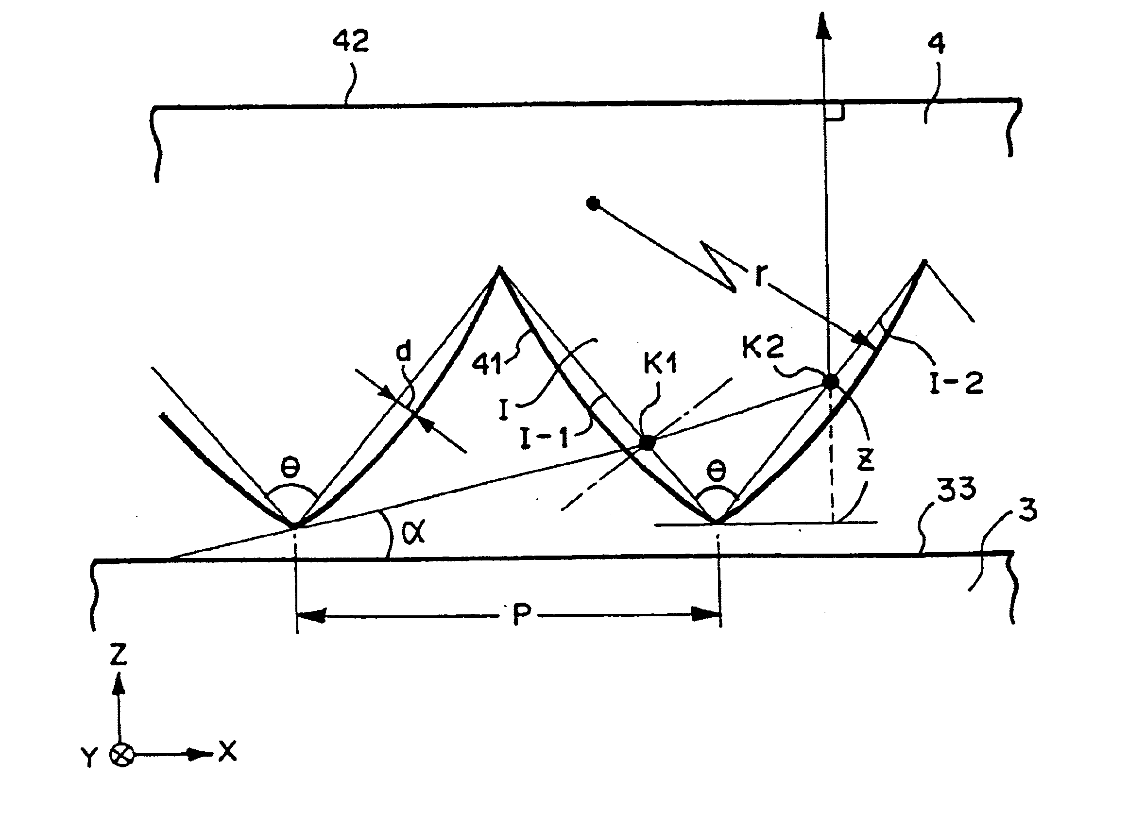
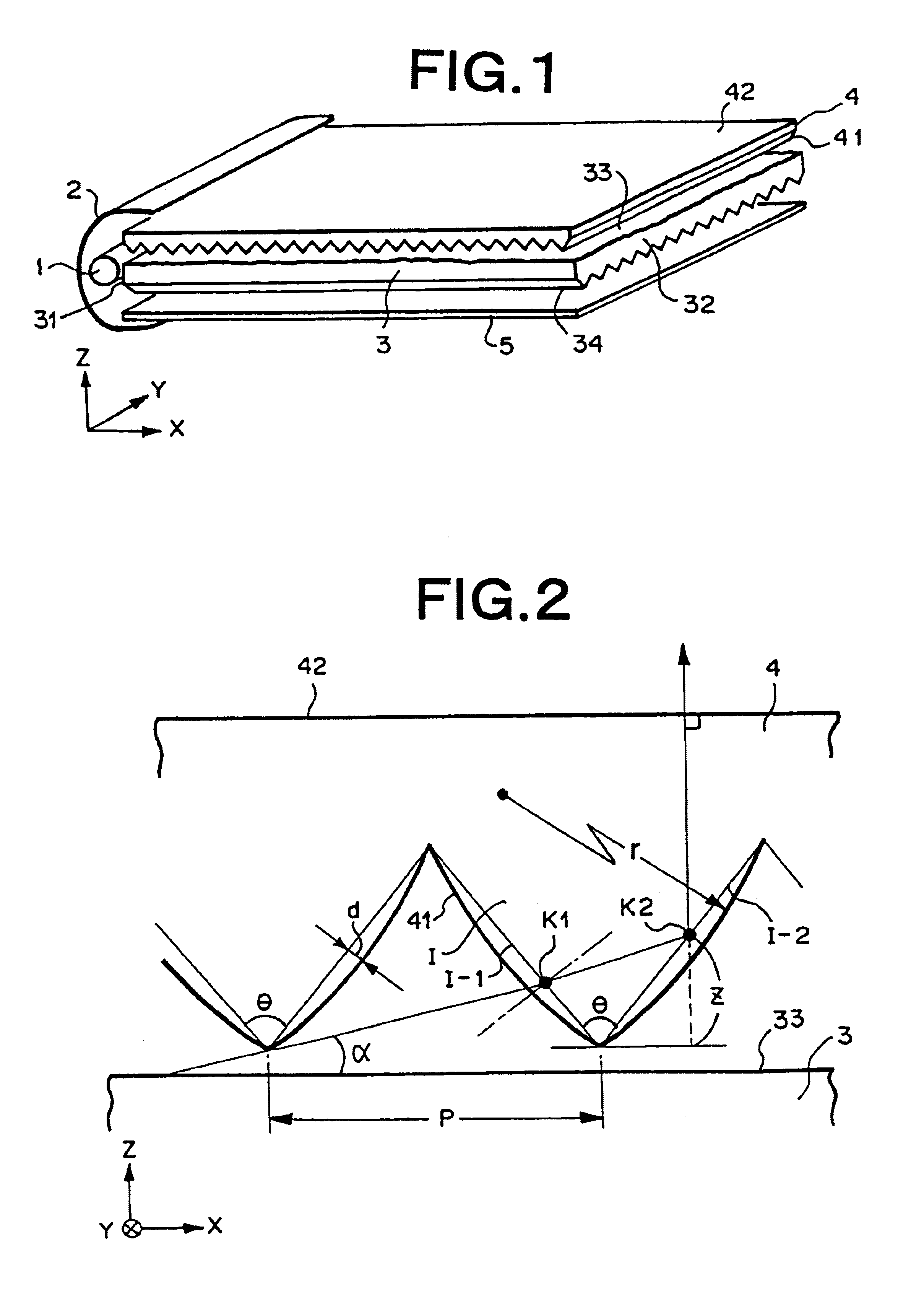
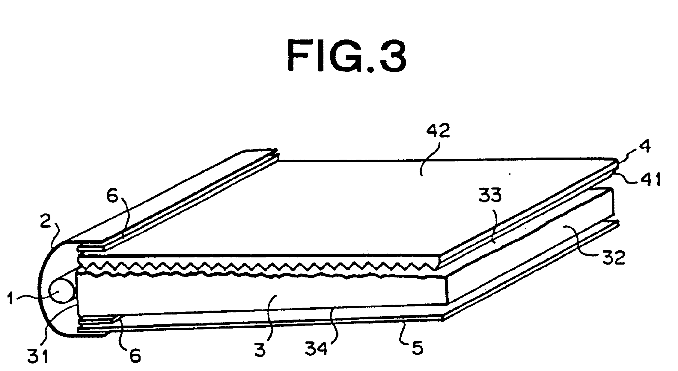
A plate-shaped light guide having a mat-finished surface (average slant angle of 3.0 degrees) on one surface thereof was formed by injection molding of acrylic resin (ACRYPET VH5#000 produced by Mitsubishi Rayon Co., Ltd.). The light guide was a wedged plate of 195 mm×253 mm in size and 3 mm-1 mm in thickness. A prism layer comprising elongated prisms made of acrylic ultraviolet curable resin having a vertical angle of 140° and a pitch of 50 μm was formed on the mirror surface side of the light guide so that the elongated prisms were continuously arranged in parallel to one another and in parallel to one side (short side: 195 mm in length) of the light guide. Further, a cold cathode tube was disposed along the long side (253 mm in length) of the light guide so as to confront one side end surface (at a side of light guide's thickness of 3 mm) corresponding to the long side of the light guide while it was covered by a light source reflector (silver reflecting film produced by Reiko Co...

example 2

A plate-shaped light guide having a mat-finished surface (average slant angle of 8.0 degrees) on one surface thereof was formed by injection molding of acrylic resin (ACRYPET VH5#000 produced by Mitsubishi Rayon Co., Ltd.). The light guide was a wedged plate of 195 mm×253 mm in size and 3 mm−1 mm in thickness. A prism layer comprising elongated prisms made of acrylic ultraviolet curable resin having a vertical angle of 140° and a pitch of 50 μm was formed on the mirror surface side of the light guide so that the elongated prisms were continuously arranged in parallel to one another and in parallel to one side (short side: 195 mm in length) of the light guide. Further, a cold cathode tube was disposed along the long side (253 mm in length) of the light guide so as to confront one side end surface (at a side of light guide's thickness of 3 mm) corresponding to the long side of the light guide while it was covered by a light source reflector (silver reflecting film produced by Reiko Co...


PUM


Abstract

A light source device having a light guide (3) for guiding light emitted from a primary light source and emitting light obliquely from a light emission face (33) thereof, and a light deflecting device (4) disposed so as to be adjacent to the light emission face. Plural elongated prisms are arranged in parallel to one another at a light incident surface (41) of the light deflecting device. Virtual elongated prisms (I) each having a vertical angle θ of 50 to 70° arranged in the same arrangement pitch as the elongated prisms are assumed so that the peak emission light in the light emission distribution of light emitted from the light emission face is incident on one virtual prism face of the virtual elongated prism, internally totally reflected by another virtual prism face and then emitted in a desired direction from a light emission surface (42) of the light deflecting device. A prism face of each elongated prism at the far side from the primary light source is designed to have a convex surface shape with respect to the shape of the virtual elongated prism. The value (r / P) of the radius of curvature r normalized by the arrangement pitch P is equal to 7 to 30, and the ratio (d / P) of the maximum distance between the convex-surface-shaped prism face of the elongated prism and the virtual prism face to the arrangement pitch P is equal to 0.05 to 5%.

Description

FIELD OF THE INVENTIONThe present invention relates to an edge-lighting type light source device constituting a liquid crystal display device or the like which is used as a display device for a portable note-type personal computer, a liquid crystal television or the like, and particularly to an improvement of a light deflecting device arranged at a light emission face side of a light guide.DESCRIPTION OF THE RELATED ARTRecently, color liquid crystal display devices have been broadly used as monitors for a portable note-type personal computer, a personal computer, etc. or as display devices for a liquid crystal television, a video-installed liquid crystal television, etc. in various fields. Further, increase of the amount of information to be processed, diversity of needs, requirements of supporting multimedia are positively promoting enlargement of the screens and enhancement of high definition in the liquid crystal display devices.A liquid crystal display device is basically constr...

Claims


Application Information

Patent Timeline
Patent Type & Authority Patents(United States)
IPC IPC(8): F21V8/00G02B5/04G02B6/00
CPCG02B5/045G02B6/0053G02B6/0046G02B6/0038G02F1/1335
Inventor YAMASHITA, TOMOYOSHICHIBA, ISSEI
Owner MITSUBISHI RAYON CO LTD
Learn More