Method for creating a coupling between a device and an ear structure in an implantable hearing assistance device

a technology of ear structure and implantable components, which is applied in the direction of deaf-aid sets, electrical devices, etc., can solve the problems of conductive hearing loss, difficulty in detecting, and requiring extremely fine adjustments

Inactive Publication Date: 2005-04-05
ST CROIX MEDICAL
View PDF6 Cites 12 Cited by
  • Summary
  • Abstract
  • Description
  • Claims
  • Application Information

AI Technical Summary

Benefits of technology

In one embodiment, an adhesive material is applied to the space between the tip and the ossicle to create mechanical coupling between the transducer and the ossicle. The adhesive may be a non-compliant (that is, hard) adhesive or a compliant adhesive. The adhesive material creates a bond at its interface with the transducer tip because the dry surface of the tip allows mechanical and/or chemical bonding thereto. A thin layer of solution on the surface of the ossicle may optionally be used to prevent the adhesive

Problems solved by technology

If these three bones do not effectively communicate the mechanical energy through the middle ear, the patient suffers from a conductive hearing loss.
For those hearing systems, or portions of hearing systems, designed for complete subcranial implantation, a challenge has existed to adapt the implantable device for optimal mounting to the unique patient morphologies (including both naturally occurring as well as those created by surgical processes) among patients.
Difficulties have arisen with the use of implantable devices in facilitating the fine adjustments necessary to properly position and configure the support assembly and attached transducers so as to contact an auditory element and thus vibrate a portion of the ossicular chain.
Such devices present a particular problem in that positioning, or docking, of the transducer against the auditory element in this stable configuration requires extremely fine adjustments that are difficult given the location of the auditory elements and the attendant's lack of maneuvering room.
It may be that, in an extreme case, too much force may damage or break either the ossicle or the transducer.
It is also possible that too little force between the transducer and the ossicle may be insufficient to detect the mechanical vibration signal, and result in a complete loss of signal detection if the transducer and the ossicle become dissociated.
Such prior art devices either harm the patient by not taking into account, fully, the detrimental impact on tissue patency caused by its structural method of attachment, are nonfunctional, or lose functioning ability with drops of pressure.
Specifically, when a transducer is too loosely coupled to the

Method used


Image

  • Method for creating a coupling between a device and an ear structure in an implantable hearing assistance device
  • Method for creating a coupling between a device and an ear structure in an implantable hearing assistance device
  • Method for creating a coupling between a device and an ear structure in an implantable hearing assistance device

Examples


Embodiment Construction

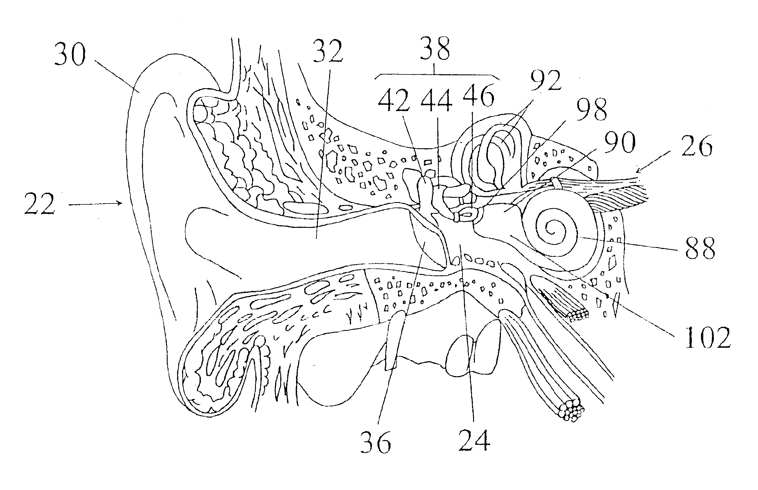
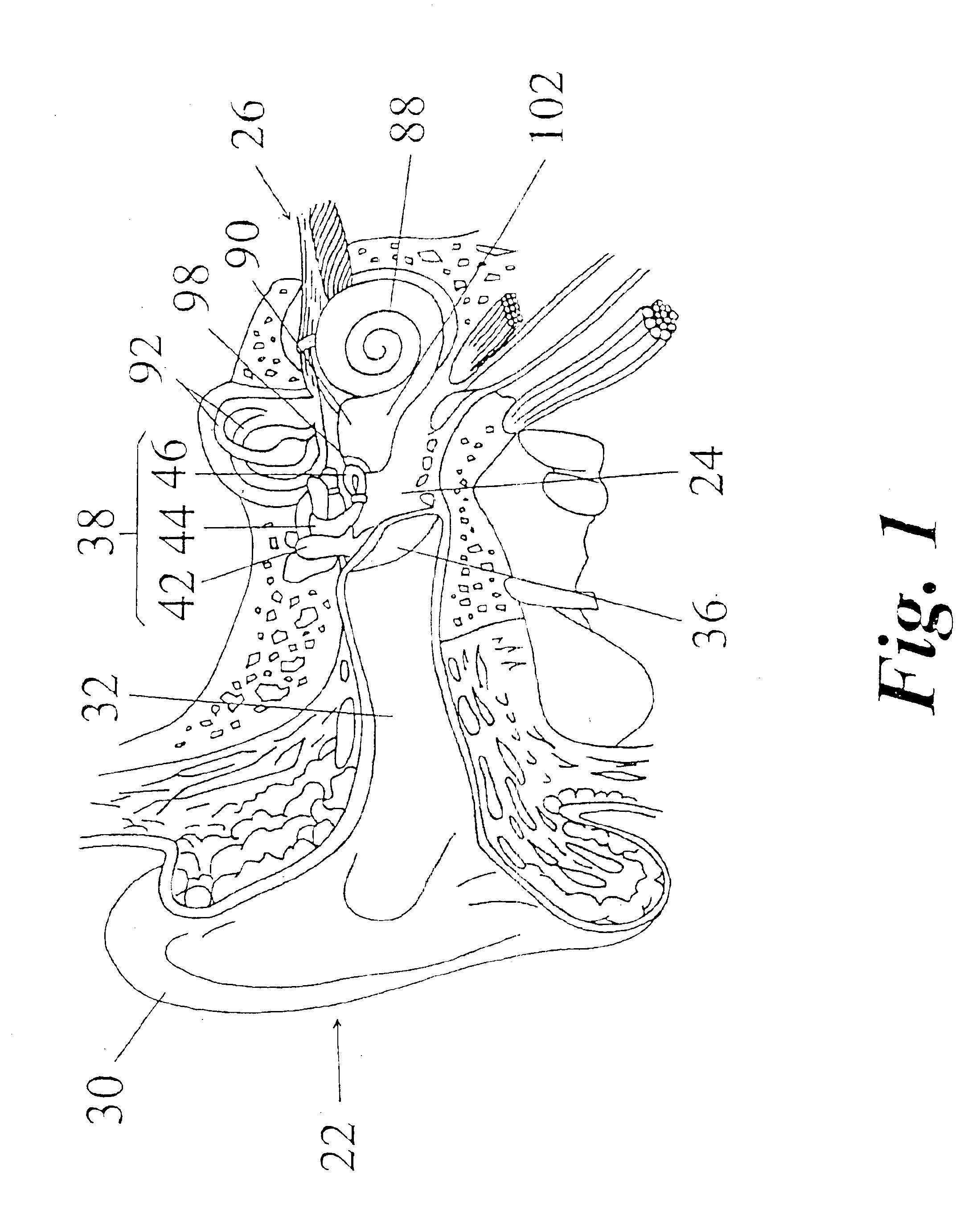
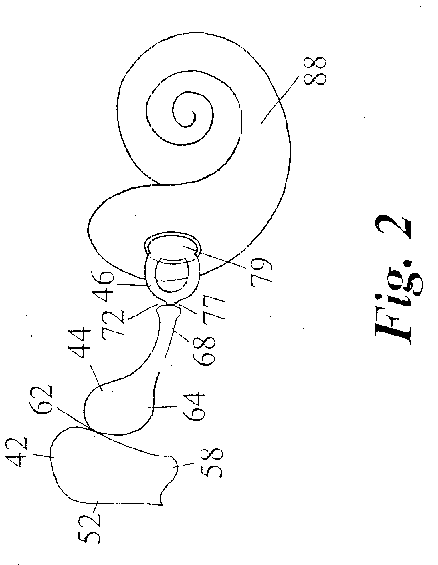
The invention provides an apparatus and method for damping vibrations in a mounting bracket assembly supporting an output transducer of an implantable hearing assistance system. Such a hearing assistance system augments the human auditory system in converting acoustic energy contained within sound waves into electromechanical signals delivered to the brain and interpreted as sound. Minimization of the undesired vibratory effect of the transducer back through component parts of the assembly improves the gain of the hearing assistance system, impairing increased hearing ability to the patient. This minimization is accomplished by providing a damping mechanism integral to the support assembly of the output transducer or, alternately, by providing a second transducer with an offsetting mass or spring or by providing a spring affixed to the support assembly.

The ear is the auditory organ of the body through which sound waves are delivered to the brain. FIG. 1 illustrates generally the sit...


PUM


Abstract

A method for creating a coupling between an implantable device, such as a transducer, and a structure of the ear, such as an ossicle, in an implantable hearing assistance device. The coupling permits slip between the device and the structure and provides a neutral load. The device is positioned such that it either lightly touches or is positioned away from the structure. In one embodiment, the surface of the device or the structure is cleaned while the remaining surface, that is, the surface not cleaned, is coated with a solution. An adhesive material is applied between the device and the structure. The solution prevents a bond from forming at that interface while a bond forms at the remaining surface. Alternatively, a compliant adhesive may be used. In another embodiment, the surface of the device is coated with a gel, the gel optionally being covered with a metallic foil.

Description

BACKGROUND OF THE INVENTION1. Field of the InventionThis invention relates to implantable hearing assistance systems for hearing impaired persons, and in particular, to a method of creating a coupling between an implantable component and a structure of the ear.2. Description of Related ArtIn a patient with normally functioning anatomical hearing structures, sound waves are directed into an ear canal by the outer ear and into contact with the tympanic membrane. The tympanic membrane is located at the terminus of the ear canal. The pressure of the sound waves (acoustic sound energy) vibrates the tympanic membrane resulting in the conversion to mechanical energy. This mechanical energy is communicated through the middle ear to the inner ear by a series of bones located in the middle ear region. These bones of the middle ear are generally referred to as the ossicular chain, which includes three primary structures, the malleus, the incus and the stapes. These three bones must be in funct...

Claims


Application Information

Patent Timeline
IPC IPC(8): H04R25/00
CPCH04R25/606
Inventor KROLL, KAIGRONDA, ANN M.SCHUGT, MIKE
Owner ST CROIX MEDICAL
Why Eureka
Try Eureka