Method for fracturing subterranean formations

a technology of subterranean formations and fracturing methods, which is applied in the direction of fluid removal, wellbore/well accessories, chemistry apparatus and processes, etc., can solve the problems of requiring special disposal procedures, affecting the speed at which a fracturing operation may be conducted, and increasing the cost of a fracturing operation, so as to reduce the amount of water required to fracture a plurality of wells in a single formation, the effect of increasing the speed of fracturing operation

Inactive Publication Date: 2005-04-05
BAKER HUGHES INC
View PDF56 Cites 163 Cited by
  • Summary
  • Abstract
  • Description
  • Claims
  • Application Information

AI Technical Summary

Benefits of technology

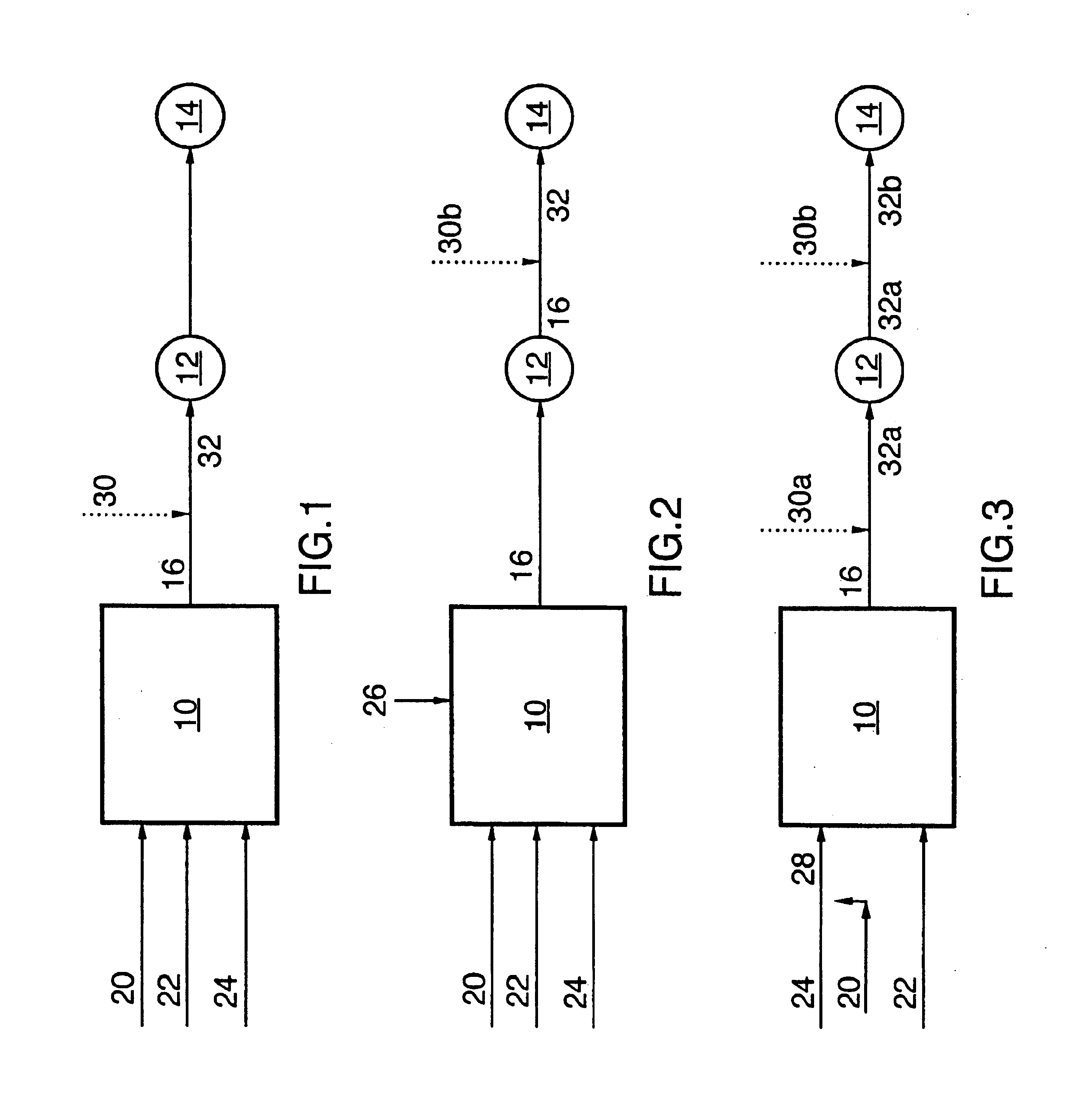
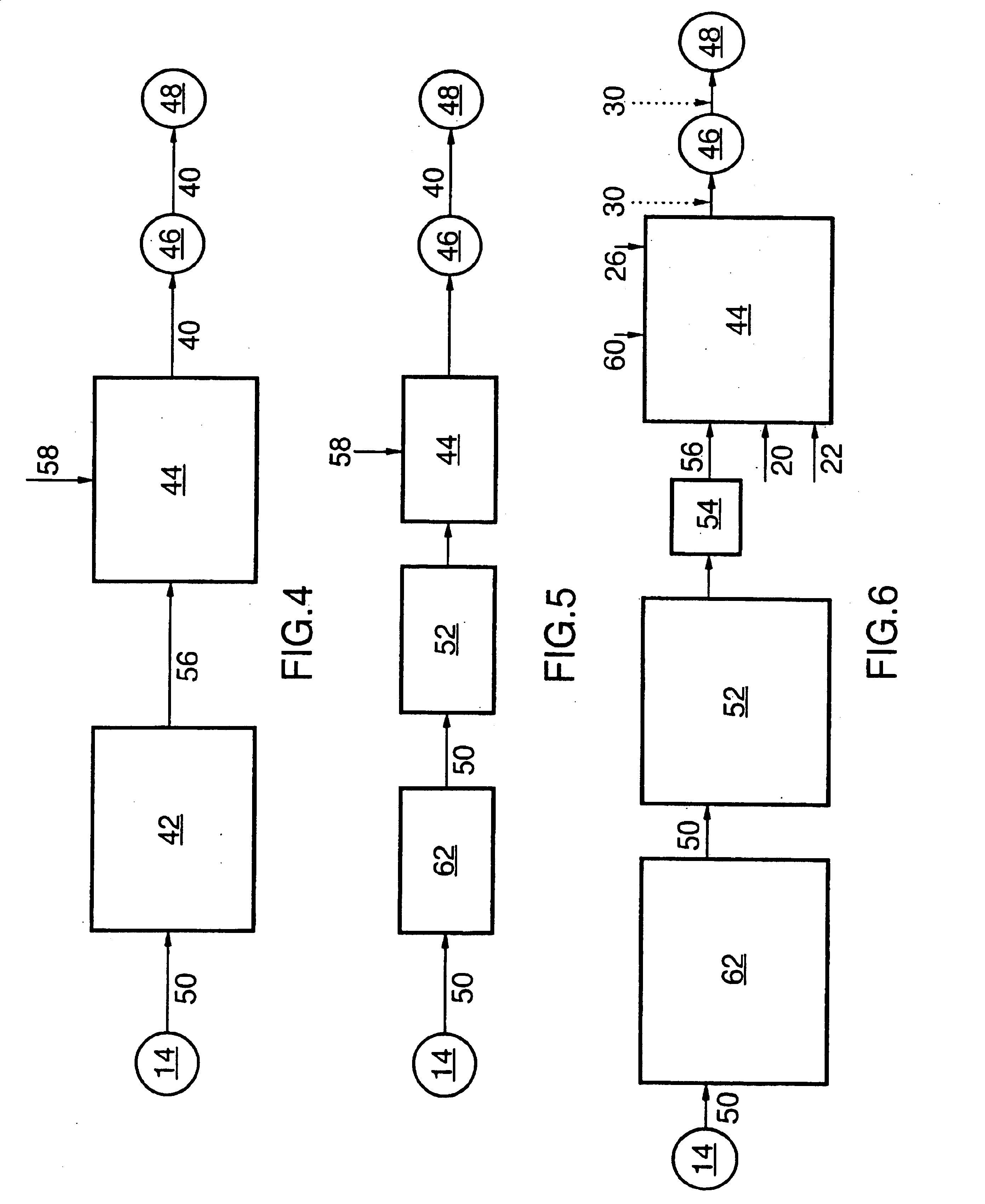
In accordance with the instance invention, a method of fracturing a formation has been developed wherein spent fracturing fluid is used to fracture additional boreholes. One advantage of the instant invention is that the amount of water which is required to fracture a plurality of boreholes in a single formation may be substantially reduced. Many oil and gas wells are positioned in remote locations which are distant to useable water supplies, thereby requiring the water for use in producing the fracturing fluid to be brought to the well site, such as by tanker trucks. This can substantially increase the cost of a fracturing operation as well as delay the speed at which a fracturing operation may be conducted. Further, spent fracturing fluid is typically considered contaminated and requires special disposal procedures (such as pumping it into an injection well or a disposal well). Reducing the total volume of spent fracturing fluid which needs to be disposed of simplifies post fracturing clean up operations.
In another embodiment, the method further comprises adding additional water to the recovered fluid to produce the amount of recycled fracturing fluid that is required for the further fracturing operation, and the additional amount of surfactant that is added to the recovered fluid is selected to replace surfactant which is removed from the first fracturing fluid during a single fracturing operation as welt as to increase the viscosity of the additional water whereby the recycled fracturing fluid has the predetermined viscosity.

Problems solved by technology

This can substantially increase the cost of a fracturing operation as well as delay the speed at which a fracturing operation may be conducted.
Further, spent fracturing fluid is typically considered contaminated and requires special disposal procedures (such as pumping it into an injection well or a disposal well).

Method used


Image

  • Method for fracturing subterranean formations
  • Method for fracturing subterranean formations
  • Method for fracturing subterranean formations

Examples


example 1

Fracturing fluids were prepared by combining N,N,N trimethyl-1-octadecammonium chloride (FAC-1X) with sodium xylene sulfonate (FAC-2X) in the concentrations which are set out below in Table 1.

TABLE 1FAC-1XFAC-1XFAC-2XFAC-2XL / m3%L / m3%3.00.33.00.37.00.75.50.5510.01.08.00.815.01.510.01.020.02.013.01.325.02.514.51.4530.03.018.01.835.03.520.02.040.04.020.52.05

In each case, the surfactants were mixed with water and then blended together with an overhead blender at low speed. The resulting fluid was placed in a pressured Fann 50 rheometer and the viscosity measured over a measured range of temperatures The results are set out in FIG. 7.

It will be understood that the data presented in FIG. 7 is exemplary in nature As can be seen from FIG. 7 a wide range of concentrations of anionic surfactants and surfactants containing a cationic group will result in gels having a high viscosity.

example 2

A viscoelastic fracturing fluid was prepared by mixing N,N,N trimethyl-1-octadecammonium chloride and sodium xylene sulphonate at a loading rate of 4 litres per cubic metre each. The resultant fracturing fluid had a viscosity on Fann 35 at 100 rpm of 5 cP, at 300 rpm of 7 cP and at 600 rpm of 10 cP. Proppant was added to the fracturing fluid at a rate of 1600 kg / m3 of clean fluid and the fracturing fluid was energized by injecting CO2 therein. The energized fluid was then pumped into a borehole and used to conduct a standard fracturing operation. After the fracturing operation, the flow back fluid was collected and pumped into a tank. The recovered fluid was subjected to a settling operation for about 24 hours during which time sand and fines in the recovered fluid settled out. Eighty per cent of the recovered fluid was then used for producing recycled fracturing fluid.

The volume of fluid required for a fracturing operation for the next borehole was determined and a sufficient amoun...

example 3

In order to demonstrate the effectiveness of a surfactant according to the instant invention to stabilize fines in a borehole, a capillary section test was conducted as is known in the industry. Pursuant to the test, a core sample from a Viking core which are known to contain clay fines was ground to a fine powder. Various fracturing fluids were prepared. Ground core sample was added at a rate of 2 g of the fine powder to 25 ml of the fracturing fluid The mixture was then stirred for 20 minutes to obtain a mixed solution at the end of 20 minutes 2 ml of the mixed solution was placed in a capillary suction test cell to commence the test. The test cell was in contact with a sheet of blotting paper. 2 wires (electrodes) were affixed to the blotting paper. Water is pulled from the test cell by capillary action and the time required for the water to move between the first and second wires is measured. The water coming into contact with the first wire (electrode) starts an electronic time...


PUM

PropertyMeasurementUnit
temperatureaaaaaaaaaa
viscosityaaaaaaaaaa
viscosityaaaaaaaaaa

Abstract

A method of fracturing a formation with a fracturing fluid wherein the formation has particulate material that swells or migrates upon exposure to the fracturing fluid comprises preparing a fracturing fluid comprising (1) a thickening compound comprising a first surfactant selected from the group consisting of a cationic surfactant having only a single cationic group, an amphoteric surfactant and a mixture thereof; and, an anionic surfactant; and, (2) water, wherein no or essentially no inorganic salt is added to the fracturing fluid; and using the fracturing fluid to fracture the formation. A method for recycling a fracturing fluid is also provided.

Description

FIELD OF THE INVENTIONThe present invention relates to the field of fracturing subterranean formations, such as the formations for the oil and gas wells, to increase their permeability and thereby increase the potential flow of recoverable hydrocarbons therefrom.BACKGROUND OF THE INVENTIONIn order to improve the recovery of hydrocarbons from oil and gas wells, the subterranean formations surrounding such wells can be fractured. That is, fluid can be introduced into the formations through one or more of well bores, at an elevated pressure (and preferably a pressure sufficiently high to initiate hydraulic fracturing, e.g., 5-120 Mpa) to open the pores and cracks in the formation. The fracturing fluids which are used in this operation are preferably loaded with proppants. Proppants may be any particles of hard material such as sand, which wedge open cracks or pores in the formation, and thereby increase the permeability of the formation once the pressure in the boreholes produced durin...

Claims


Application Information

Patent Timeline
Patent Type & Authority Patents(United States)
IPC IPC(8): C09K8/60C09K8/62
CPCC09K8/62Y10S507/922
Inventor GUPTA, D. V. SATYANARAYANATUDOR, ERIC HUGHSON
Owner BAKER HUGHES INC
Why Eureka
Try Eureka