Electric heating system for a motor vehicle

Inactive Publication Date: 2005-04-05
BORGWARNER BERU SYST
View PDF12 Cites 29 Cited by
  • Summary
  • Abstract
  • Description
  • Claims
  • Application Information

AI Technical Summary

Benefits of technology

Now, it is the object of the present invention to show a way how the protection of the control circuit and the electric safety of an electric heating system for a motor vehicle

Problems solved by technology

It is a fundamental problem connected with the object to be achieved that the heat-dissipating mounting surfaces of the power semiconductors, which guide and connect the current for the heating elements, are connected to positive potential whereas the heat sinks should be connected to ground potential for safety reasons.

Method used


Image

  • Electric heating system for a motor vehicle
  • Electric heating system for a motor vehicle
  • Electric heating system for a motor vehicle

Examples


Example

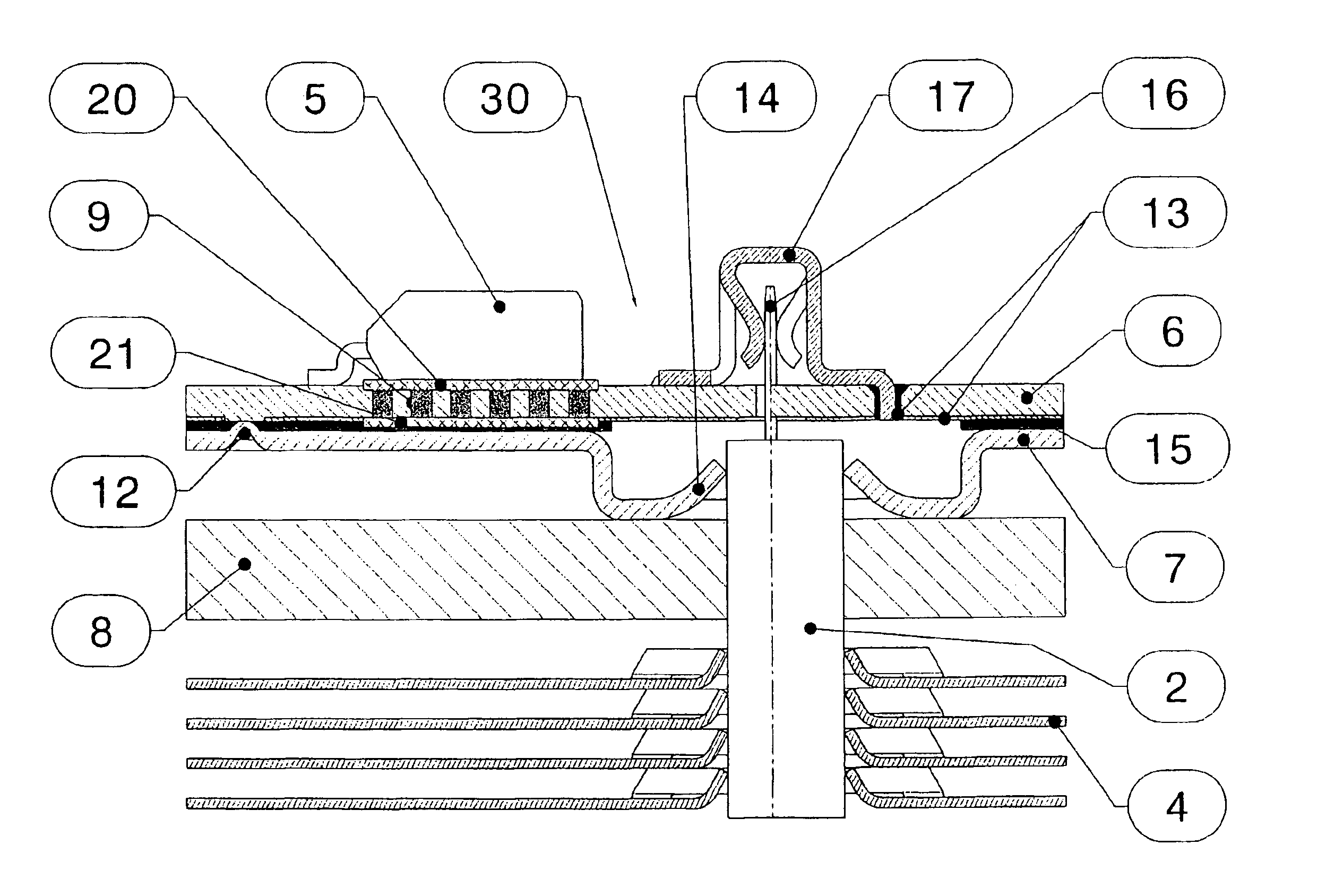
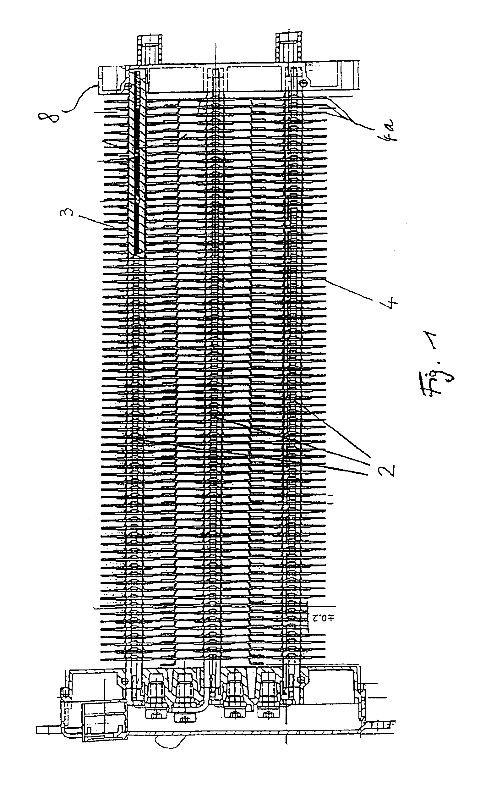
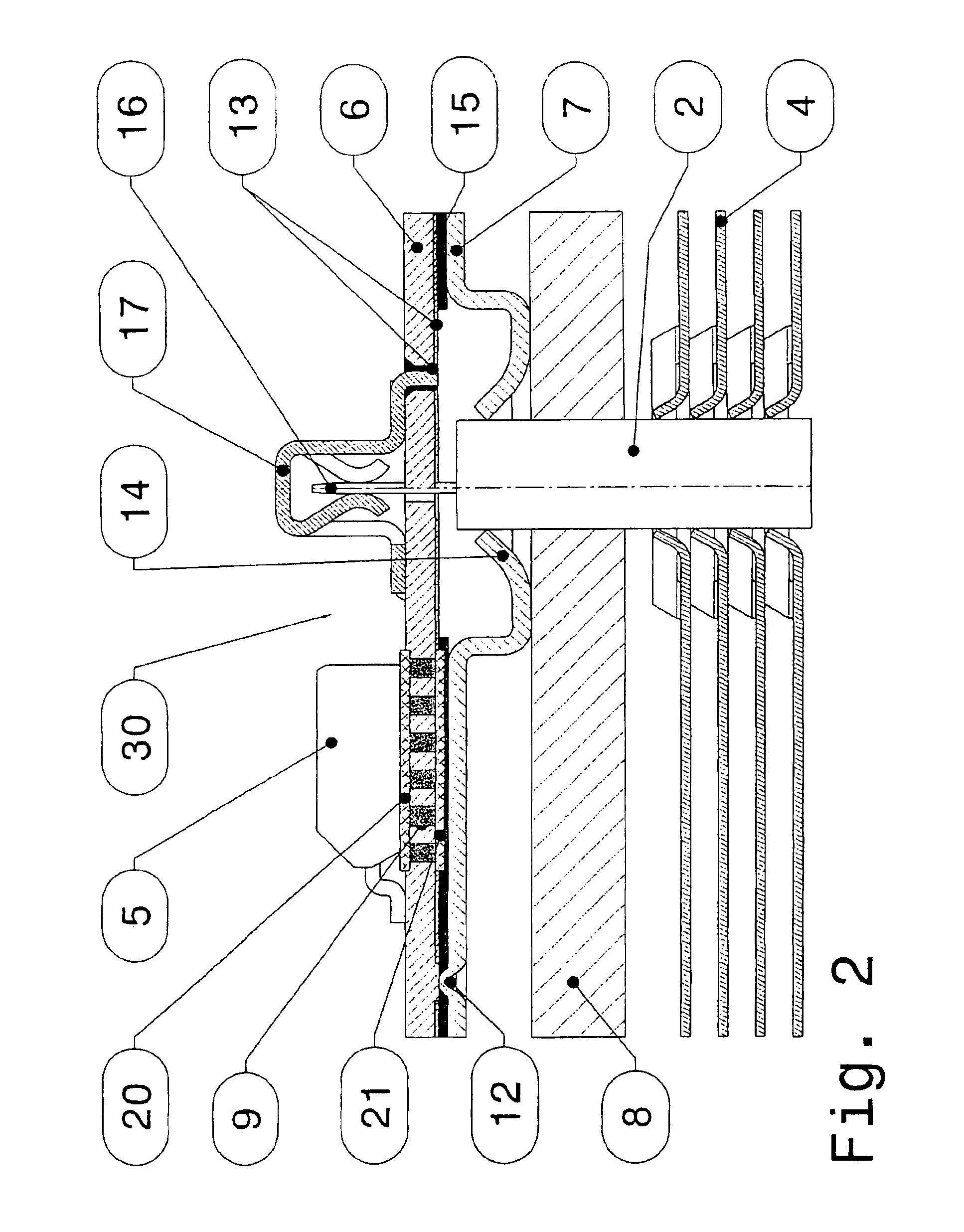
FIG. 1 shows the heating rods 2, filled with PTC heating elements 3, as well as the relevant heat-dissipating means 4, which take the form of sheet-metal bars that have been pushed onto the heating rods 2 in clamping relationship, for one practical embodiment of an electric heating system for a motor vehicle. In operation of the electric heating system, an air current to be heated flows around the heating rods 2 and the respective heat-dissipating means 4, whereby heat is transmitted to the air current. It is an advantage in this connection that during that process there is transmitted to the air current not only the heat generated by the PTC heating elements 3, but also the heat generated by the components of a control circuit 30 provided in the housing 8. This not only prevents overheating of the control circuit provided in the housing 8, but also improves the efficiency of the electric heating system. The heat-dissipating means 4a serve to carry off the heat generated by the comp...


PUM

PropertyMeasurementUnit
Thicknessaaaaaaaaaa
Thicknessaaaaaaaaaa
Poweraaaaaaaaaa

Abstract

An electric heating system for motor vehicles including one or several electric heating elements; a control circuit provided for controlling the power dissipated by the heating elements; the control circuit including one or several power semiconductors arranged on a circuit board; the circuit board is by means of a solid matter connection connected by the side facing away from the power semiconductors to a metal plate intended to be mass potential; the metal plate being electrically insulated from conductor paths located on the underside of the circuit board and intended to carry a voltage in relation to the ground potential; the control circuit being arranged in a housing. One or several heat sinks are provided outside the housing. The metal plate is connected with the heat sinks arranged outside the housing by thermally conductive connectors.

Description

BACKGROUND OF THE INVENTION1. Field of the InventionThe present invention relates to an electric heating system for a motor vehicle.2. Description of the Related ArtA heating system of that kind has been known from DE 199 02 050 A1 as an auxiliary heating system for a motor vehicle that is driven by a combustion engine. As a rule, motor vehicle heating systems utilize the waste heat produced by the combustion engine. However, the continuous progress made in increasing the efficiency of combustion engines has resulted in reducing the amount of waste heat available for the heating system. This is true especially for those direct-injection diesel engines which are designed especially for fuel economy. Due to their small yield of waste heat, these engines do not, especially in winter times, warm up the vehicle as quickly as would be desirable for defrosting the windscreen, to prevent fogging of the windscreen and to heat up the passenger compartment to a comfortable temperature. It is, ...

Claims


Application Information

Patent Timeline
IPC IPC(8): B60H1/03B60H1/02B60H1/22H05K1/02H05K3/40H05K3/38B60H1/00
CPCB60H1/034B60H1/2225H05K1/0206H05K3/0061H05K3/386H05K2203/0315H05K2201/0305H05K2201/0382H05K2201/10166H05K2201/2036H05K3/4038F24H3/0441
Inventor UHL, GUNTHERGEIGER, STEFFENALBAN, THOMASGIFFELS, THOMASWENSKE, DIRKHAMBURGER, ANDREASRIETHER, MIKE
Owner BORGWARNER BERU SYST
Why Eureka
Try Eureka