
Claw-pole type stepping motor having radial dimension reduced without detriment to performance characteristic

a stepping motor and radial dimension technology, applied in the direction of horology, magnetism circuit shape/form/construction, instruments, etc., can solve the problems of small motor, and inability to reduce the radial dimension without detriment to the performance characteristic, so as to reduce the difficulty and troublesomeness of assembling work, reduce the diameter of the motor, and improve the effect of assembling work

Inactive Publication Date: 2005-04-05
MINEBEA CO LTD
View PDF7 Cites 20 Cited by
  • Summary
  • Abstract
  • Description
  • Claims
  • Application Information

AI Technical Summary

Benefits of technology

The present invention is a claw-pole type stepping motor that reduces difficulty and troublesomeness in assembling work, and which enables reduction of the motor diameter without detriment to the motor performance characteristic. The motor is structured by a rotor and two stators, each with at least one magnetic coil. The statists are held together in place by a pin that goes axially through them. This eliminates the need for an outer ring and reduces the radial dimension of the motor without sacrificing the motor performance characteristic. The at least one pin can be riveted to securely hold the statists together. The pin can be hollow to make riveting easy with a light force.

Problems solved by technology

Accordingly, a rotor magnet in a motor with a small radial dimension is forced to be small in diameter, and therefore the motor characteristic is inevitably degraded significantly.
In such a case, a brushless DC motor provided with an encoder as a position detector must be used for position control in place of a claw-pole type stepping motor, and this invites cost increase.
Such a small motor, however, is very difficult and troublesome to assemble just because of its reduced radial dimension and resultantly increased axial dimension, especially when a large number of components are used.

Method used


Image

  • Claw-pole type stepping motor having radial dimension reduced without detriment to performance characteristic
  • Claw-pole type stepping motor having radial dimension reduced without detriment to performance characteristic
  • Claw-pole type stepping motor having radial dimension reduced without detriment to performance characteristic

Examples


Embodiment Construction

An embodiment of the present invention will hereinafter be described with reference to the accompanying drawings.

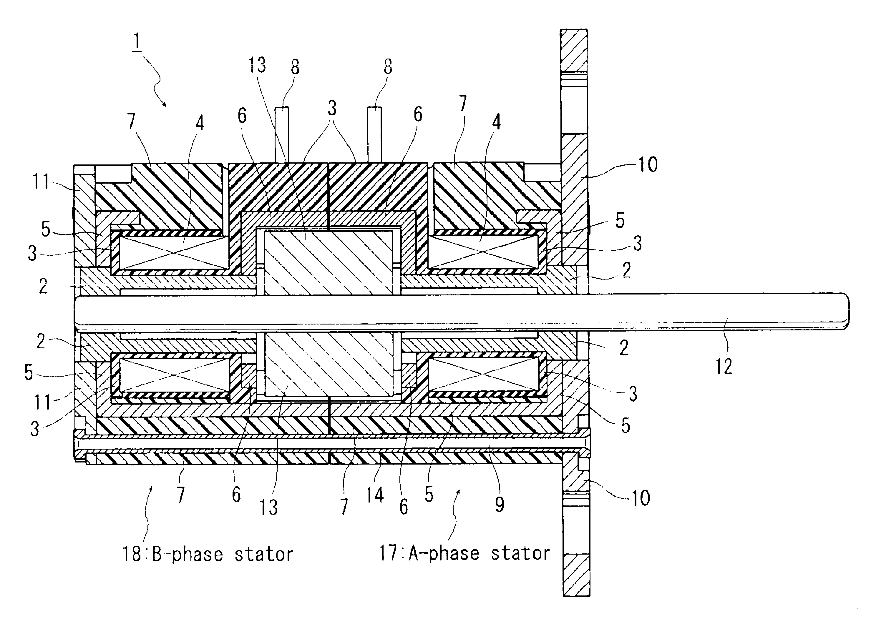
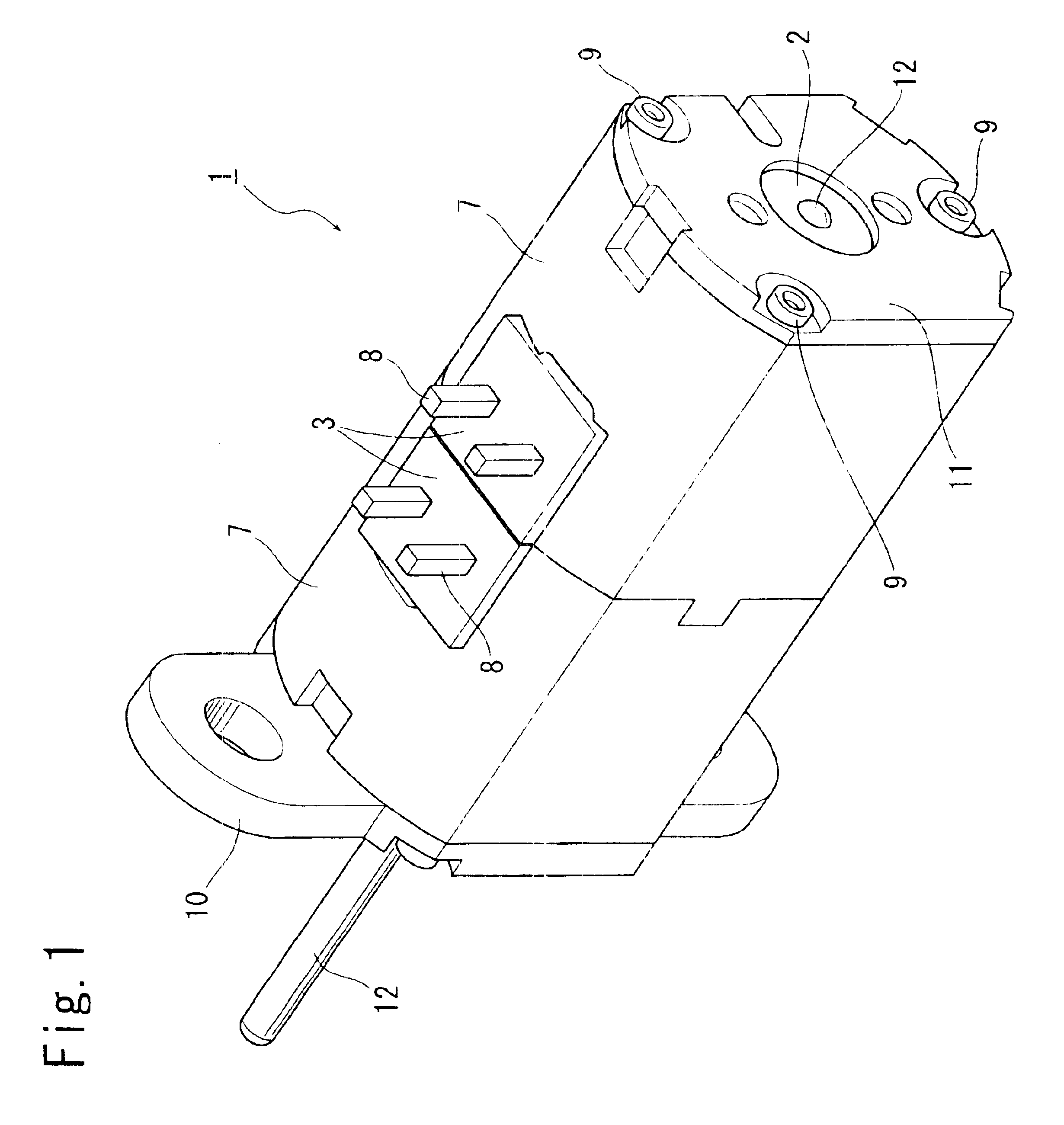
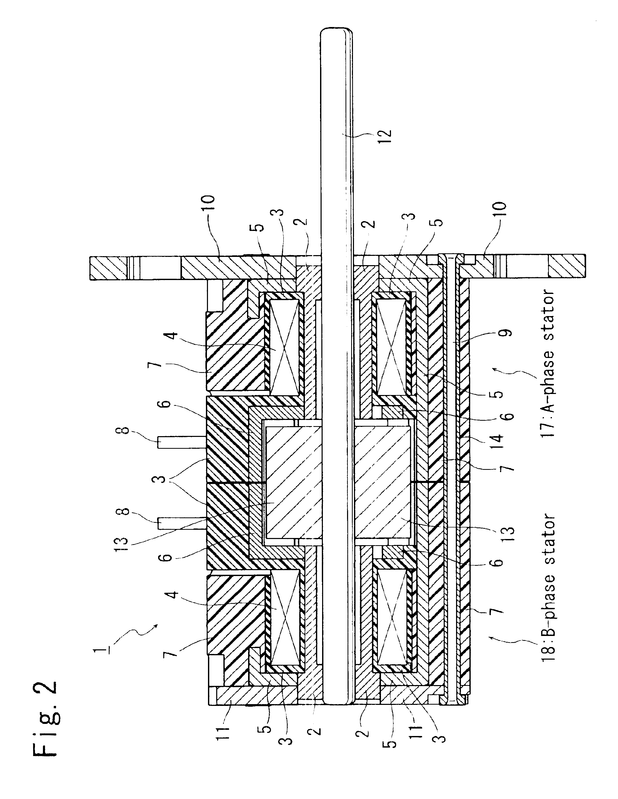
A claw-pole type stepping motor 1 according to the embodiment of the present invention is shown in FIG. 1. Referring now to FIG. 2, the claw-pole type stepping motor 1 basically comprises: a rotor composed of a rotary shaft 12, and a rotor magnet 13 made of, for example, a cylindrical magnetic material; and A-phase and B-phase stators 17 and 18 including respective magnetic coils 4 and coupled to each other with their magnetic coils 4 located respectively toward the both axial end faces of the rotor magnet 13. The A-phase and B-phase stators 17 and 18 may be composed of common components so as to be constructed identical with each other, whereby production cost of the components can be reduced.

The rotor is rotatably housed in the A-phase and B-phase stators 17 and 18 such that the rotor magnet 13 is axially sandwiched by the magnetic coils 4 as shown in FIG. 2, and is cir...


PUM


Abstract

A claw-pole type stepping motor comprises: a rotor which is shaped substantially cylindrical, and which has a rotary shaft at its radial center; and two stators which are shaped like a cup, each have at least one magnetic coil, are coupled to each other so as to rotatably house the rotor with their magnetic coils located respectively toward both axial end faces of the rotor, and which each have two pole tooth arrays magnetically connected to each other such that magnetic phase difference therebetween at tips of respective pole teeth is 180 degrees in terms of electrical angle, and in the motor thus structure, three pipes of aluminum go axially through the two stators so as to hold together the two stators.

Description

This application priority from Japan Application No.2003-193329, filed Jul. 8, 2003 (incorporated by reference herein).BACKGROUND OF THE INVENTION1. Field of the InventionThe present invention relates to a claw-pole type stepping motor, and particularly to a structure of a claw-pole type stepping motor, which enables reduction in radial dimension and improvement in performance characteristic.2. Description of the Related ArtDue to increasing demand for miniaturization of various electronics devices, motors used in the electronics devices are also requested to be downsized increasingly. In a conventional claw-pole type stepping motor of inner rotor structure, magnetic coils of A phase and B phase are typically disposed so as to circumferentially surround a rotor. In such a claw-pole type stepping motor, the outer diameter of a rotor magnet is restricted by the inner diameter of a stator. Accordingly, a rotor magnet in a motor with a small radial dimension is forced to be small in dia...

Claims


Application Information

Patent Timeline
Patent Type & Authority Patents(United States)
IPC IPC(8): H02K37/12H02K5/15H02K1/14H02K5/04H02K37/14
CPCH02K1/145H02K37/12H02K5/15H02K5/04
Inventor MATSUSHITA, KUNITAKEYAMAWAKI, TAKAYUKINAGATA, TOSHIHIKOHARADA, NAOYUKI
Owner MINEBEA CO LTD
Learn More