Eureka AIR delivers breakthrough ideas for toughest innovation challenges, trusted by R&D personnel around the world.

Method and controller for field weakening operation of AC machines

Inactive Publication Date: 2005-04-05
DELPHI TECH IP LTD
View PDF17 Cites 25 Cited by
  • Summary
  • Abstract
  • Description
  • Claims
  • Application Information

AI Technical Summary

Benefits of technology

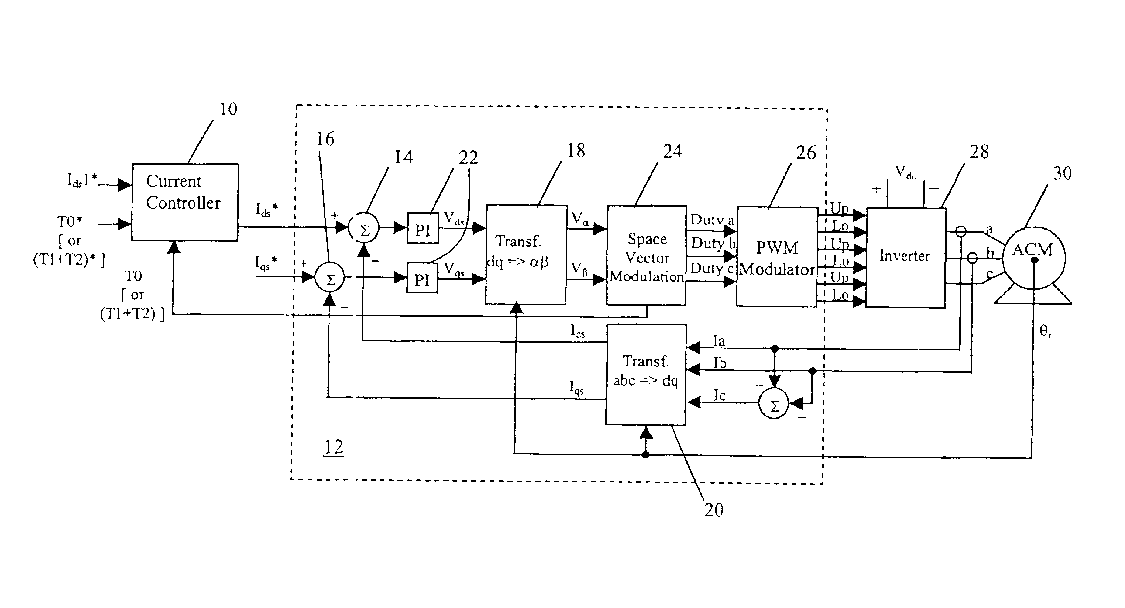
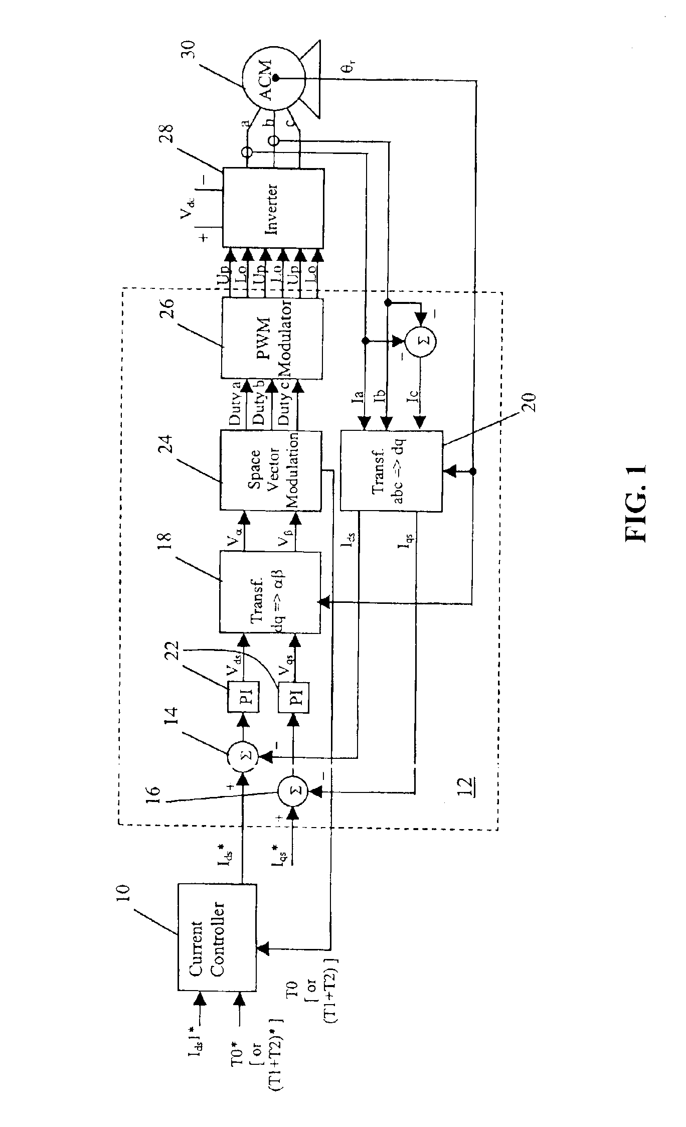
[0010]The present invention further fulfills the foregoing needs by providing, in another aspect thereof, a current controller for an electric machine. The current controller includes a state vector error comparator for comparing a received state vector time signal to a commanded state

Problems solved by technology

However, such motors typically exhibit nonlinear characteristics and parameter variations due to temperature, magnetic saturation, or both, when operated over a wide operating range.
In addition, the variation of drive input values, such as battery voltage, can negatively affect the motor performance and can cause loss of motor control.
This condition results in operation where the controller operates the machine near the voltage limit of the system.
The dynamics of the control may be of paramount importance since operation in the voltage limited condition could cause certain undesirable effects, such as voltage saturation, that can cause slow response or loss of machine control.
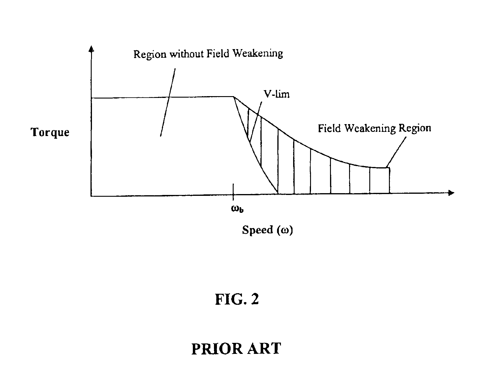
In the field-weakened range, the torque and efficiency are limited by the available bus voltage.
If too little current is used to weaken the field for a PMAC machine or, analogously, if too much flux current is used in a SyR machine or an induction machine, then control can be lost due to voltage limit conditions.
In contrast, if too much current is provided in a PMAC machine or, analogously if too little flux current is used in a SyR machine or an induction machine, then the efficiency will be too low.
While look-up tables have been proposed to perform this function, the values stored in the table may not be valid under dynamically changing operating condition.

Method used


Image

  • Method and controller for field weakening operation of AC machines
  • Method and controller for field weakening operation of AC machines
  • Method and controller for field weakening operation of AC machines

Examples


Embodiment Construction

ency or ease of maintenance, the ordering of the blocks of the illustrated flow charts could be rearranged or moved inside or outside of the illustrated loops by one skilled in the art. While the present invention will be described with reference to the details of the embodiments of the invention shown in the drawing, these details are not intended to limit the scope of the invention.

DETAILED DESCRIPTION OF THE INVENTION

[0019]In general, a current controller embodying aspects of the present invention controls a d-axis current provided to an alternating current (AC) machine controller. In particular, the invention dynamically controls the d-axis current to limit the back EMF generated by the AC machine when the machine is operating in the field-weakening region. In an aspect of the invention, the current regulator can use either the state vector T0 or the sum of state vectors T1 and T2 (T1+T2) [where T0=1−(T1+T2), 000 or (T1+T2), where the sum of T1 and T2 is proportional to the phas...


PUM


Abstract

Method for providing current regulation and a current controller (10) for an electric machine (30) are provided. The method includes receiving a state vector time signal (36) indicative of a time interval when a switching state vector is activated and comparing the received state vector time signal to a commanded state vector time signal (38). The method further includes using the result of the comparison to regulate a direct axis current signal (42, 44) input to an electric machine controller. The current controller (10) includes a state vector error comparator for comparing a received state vector time signal to a commanded state vector time signal and generating a state vector time error. This error is processed by a PI controller, coupled to the state vector error comparator, for providing a direct axis current signal output responsive to the state vector time error to an electric machine.

Description

BACKGROUND OF THE INVENTION[0002]The present invention is generally related to control of electric machines, and, more particularly, to a controller device and method for providing current control of power converter driven electric machines.[0003]To overcome the disadvantages of DC motors in DC powered applications, it is known to use synchronous machines in either the form of a permanent magnet (PMAC) wound field or a synchronous reluctance machine (SyR) or induction machine (asynchronous) in conjunction with a power inverter. However, such motors typically exhibit nonlinear characteristics and parameter variations due to temperature, magnetic saturation, or both, when operated over a wide operating range. In addition, the variation of drive input values, such as battery voltage, can negatively affect the motor performance and can cause loss of motor control. Accordingly, the use of known vector control techniques, coupled with a pulse width modulation (PWM) strategy and a power in...

Claims


Application Information

Patent Timeline
IPC IPC(8): H02P21/00H02P21/06
CPCH02P21/06H02P21/0035H02P21/22
Inventor GALLEGOS-LOPEZ, GABRIELWALTERS, JAMES E.GUNAWAN, FANI S.
Owner DELPHI TECH IP LTD
Why Eureka
Eureka Blog
Learn More