Apparatus and method for power ramp up of wireless modem transmitter

a wireless modem and transmitter technology, applied in the direction of transmitter/receiver shaping network, transmission, synchronous/start-stop system, etc., can solve the problem of affecting the power gain of the wireless modem, the degree of control of the pa power gain, and the resultant splatter is very limited, so as to achieve better control of the ramp up curve. , the effect of better control

Inactive Publication Date: 2005-04-05
SIERRA WIRELESS
View PDF11 Cites 34 Cited by
  • Summary
  • Abstract
  • Description
  • Claims
  • Application Information

AI Technical Summary

Benefits of technology

Accordingly, it is an objective of the present invention to provide a new and improved apparatus and method for ramping up the power of a transmitter of a wireless modem.
One avenue in which the above mentioned objective is accomplished by the present invention is in obtaining much better control by using a digital-to-analog converter to generate waveforms of ramp data with desired duration and shape. A software controlled method, which may be implemented through firmware and hardware, achieves much better control of the ramp up curve than the prior available hardware implemented systems.

Problems solved by technology

A disadvantage of the aforementioned hardware driven technique is that the degree of controlling the rate of the PA power gain, and thus the resultant splatter, is very limited.
A very steep envelope slope at low power levels will not cause sufficient splatter but the same slope near the PA's maximum power will cause considerable splatter.
An RC time constant may nominally tend to do this, but the degree of controlling the rate of power increase in relation to the time rate of change of the power level is difficult and very limited when relying mainly on the hardware.
Some of the limitations of the prior art lie in its inability to effectively shorten the ramp up time while maintaining a low level of splatter between the transmitting channel and adjacent channels.
Control of the ramp up curve is difficult to achieve with hardware alone, thus resulting in overly complex digital ramp circuitry which still has not been able to meet the needs required by advancing transmission speeds.

Method used


Image

  • Apparatus and method for power ramp up of wireless modem transmitter
  • Apparatus and method for power ramp up of wireless modem transmitter
  • Apparatus and method for power ramp up of wireless modem transmitter

Examples


Embodiment Construction

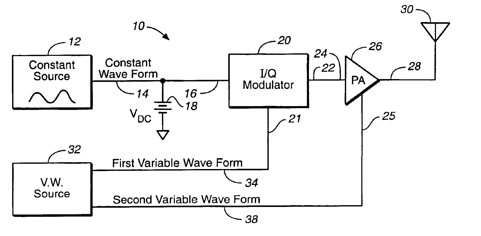
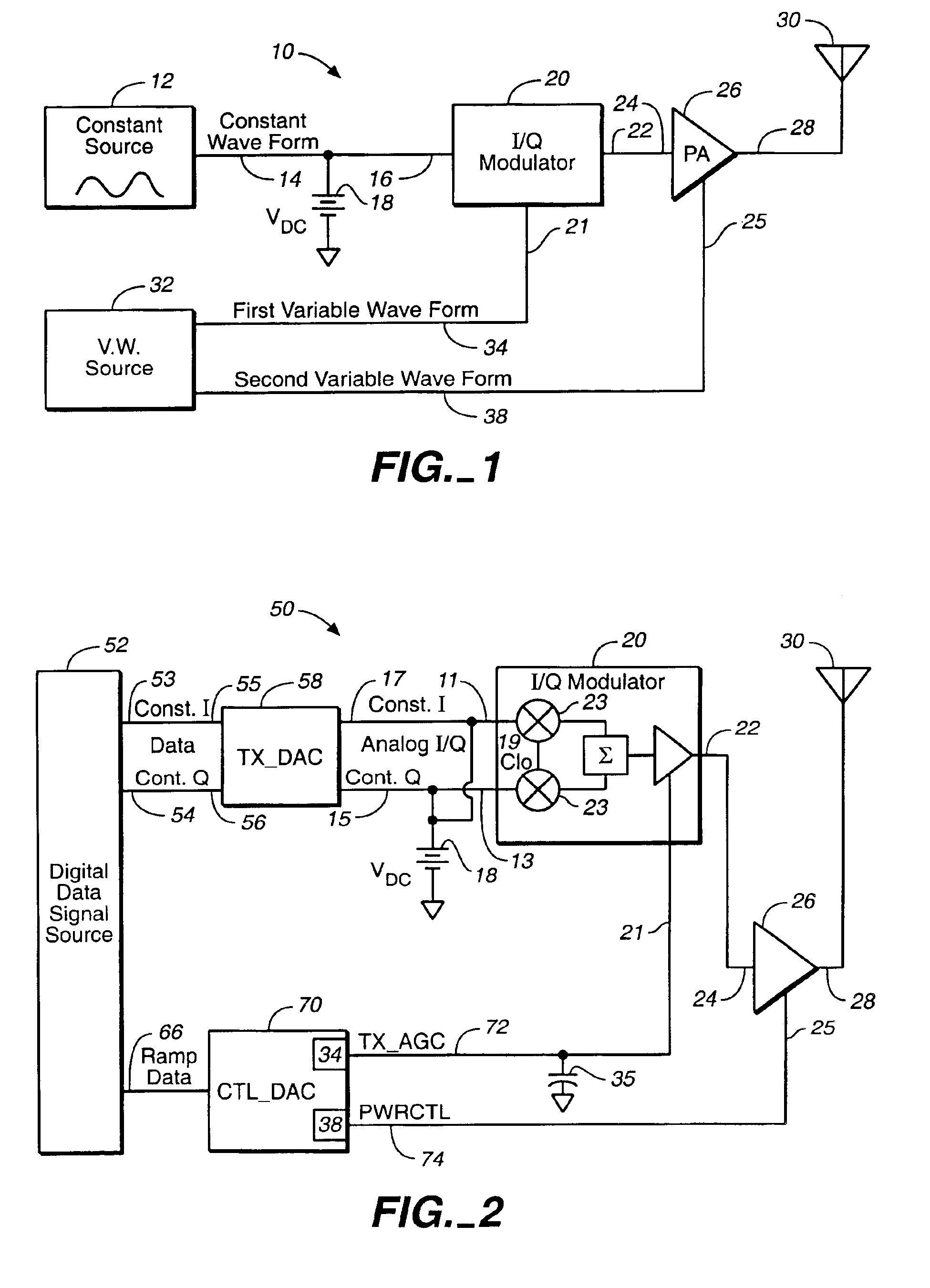
In accordance with the presently claimed invention, FIG. 1 illustrates a block / schematic diagram of a wireless modem illustrative of an embodiment of the present invention and generally designated by numeral 10. The wireless modem 10 includes a direct current (DC) bias voltage 18, a constant amplitude waveform source 12, a variable amplitude waveform source 32, an In-phase / Quadrature (I / Q) modulator 20, a power amplifier (PA) 26 and a transmitting antenna 30. The constant amplitude waveform source 12 provides a constant amplitude waveform 14 which, being coupled in common with each of a direct current (DC) voltage 18 and an input 16 of a I / Q modulator 20, may be sufficient to bias the I / Q modulator 20 to maximum gain. The I / Q modulator 20 further includes a gain control 21 and an output 22.

The variable amplitude waveform source 32 provides a first variable amplitude waveform 34 and a second variable amplitude waveform 38. The I / Q modulator output 22 is coupled with a PA input 24. Th...


PUM


Abstract

A transmitter of a wireless modem may be ramped up with quicker ramp up times and better splatter control by using software controllable ramp up techniques. A digital data signal source sends data to digital-to-analog converters used to generate a ramp with the desired duration and shape for maximum gain with minimum splatter. A transmitter digital-to-analog converter is sent constant I / Q data to bias the input of the I / Q modulator to maximum gain when combined with a direct current voltage. A controller digital-to-analog converter is sent incremented ramp data to shape the ramp and provide maximum gain at the output of the I / Q modulator.

Description

BACKGROUND OF THE INVENTION1. Field of the InventionThe present invention generally relates to wireless communications modems and, more particularly, to an apparatus and method for ramping up the transmitter power of a wireless modem.2. Description of the Related ArtWireless modems generally modulate an RF carrier with a stream of data packets, then amplify the modulated carrier for transmission from an internal antenna. When a transmitter carrier is keyed on or first brought up to full power, the transmitter is essentially being amplitude modulated from an off state to a full powered on state. The quicker the transmitter power is ramped up, the wider the spread of spurious emissions, called splatter, occur around the carrier frequency. Splatter results in the placement of unwanted energy into adjacent channels in the ISM band, 900 MHz (Industrial, Scientific and Medical band).Currently, wireless modems use hardware to reduce the level of the out of band energy, thereby lessening th...

Claims


Application Information

Patent Timeline
Patent Type & Authority Patents(United States)
IPC IPC(8): H04B1/04
CPCH04B1/0475
Inventor PETERS, KENMURRU, ENRICO
Owner SIERRA WIRELESS
Why Eureka
Try Eureka