
Mammography method and apparatus

Inactive Publication Date: 2005-04-05
XDATA CORP
View PDF23 Cites 48 Cited by
  • Summary
  • Abstract
  • Description
  • Claims
  • Application Information

AI Technical Summary

Benefits of technology

According to one aspect of the invention, a system for generating a three-dimensional image of the compressed breast of a subject includes an x-ray mammography unit for generating x-ray mammography data, a mechanical scanner including an x-ray mammography compression paddle assembly, a control and motion system for driving

Problems solved by technology

In the United States, many clinicians during the 1980s and early 1990s restricted ultrasound breast imaging to a limited role of differentiation between cystic and solid masses.
Currently, to correlate precisely standard breast ultrasound imaging data with that provided by x-ray mammography data can sometimes be impossible because the anatomical orientations of tissues traversed by the x-ray beam for the various compressed breast positions are different from the anatomical position of tissues traversed by the ultrasound beam following its entrance into an uncompressed breast in a supine position.
These problems can lead to diagnostic errors.
The thick plexiglas compression paddle was inappropriate for x-ray breast imaging because of its increased attenuation of the x-ray beam.
The thickness of the compression plate was also inappropriate for ultrasound imaging, causing increased ultrasound attenuation and multiple artifactual reflections within the breast image.
The system is not designed for ultrasound scanning of the whole breast.
The system was not designed for a precise comparison between ultrasound images and x-ray images in terms of ultrasonically imaging a breast while it is held in the same positions and under the same compression for each modality.
Overlying diagnostic features are summed together, resulting in the possibility that important information is blurred, summed, and overlaid so it cannot be detected in the x-ray image.

Method used


Image

  • Mammography method and apparatus
  • Mammography method and apparatus
  • Mammography method and apparatus

Examples


Embodiment Construction

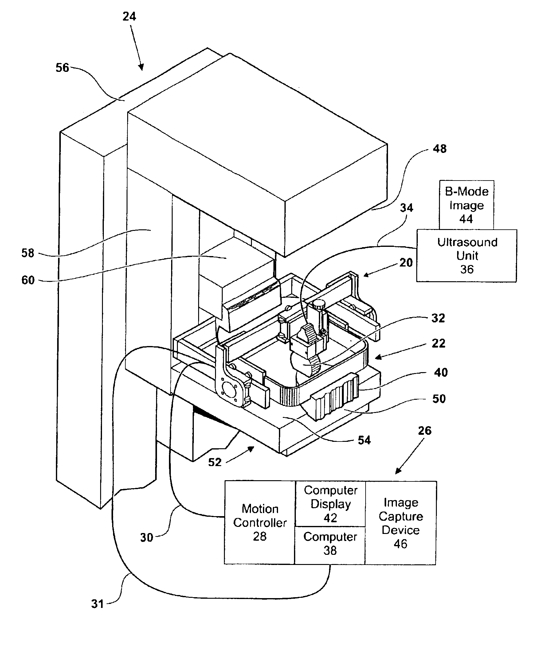
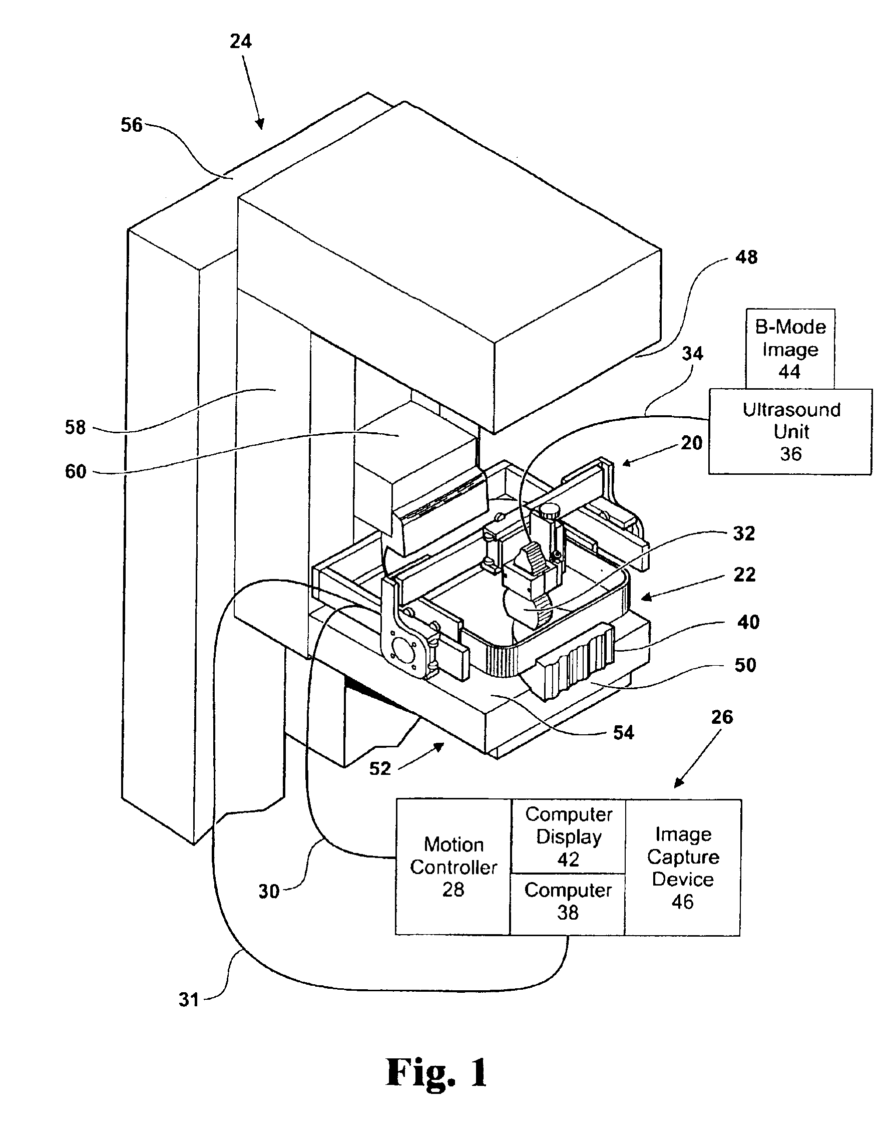
FIG. 1 illustrates a combined ultrasound and x-ray imaging system according to the present invention, as applied to multi-modal diagnostic breast imaging. The illustrated embodiment adapts medically-accepted, FDA-approved, ultrasound linear array imaging systems, x-ray mammography units, and compression paddles to realize a diagnostic imaging modality for detection and assessment of breast cancer and other breast abnormalities. The modality combines two-dimensional x-ray imaging with three-dimensional ultrasound imaging, with the breast immobilized in the same configuration for both. Ultrasound and x-ray views of abnormalities are thus spatially registered, simplifying interpretation of breast masses.

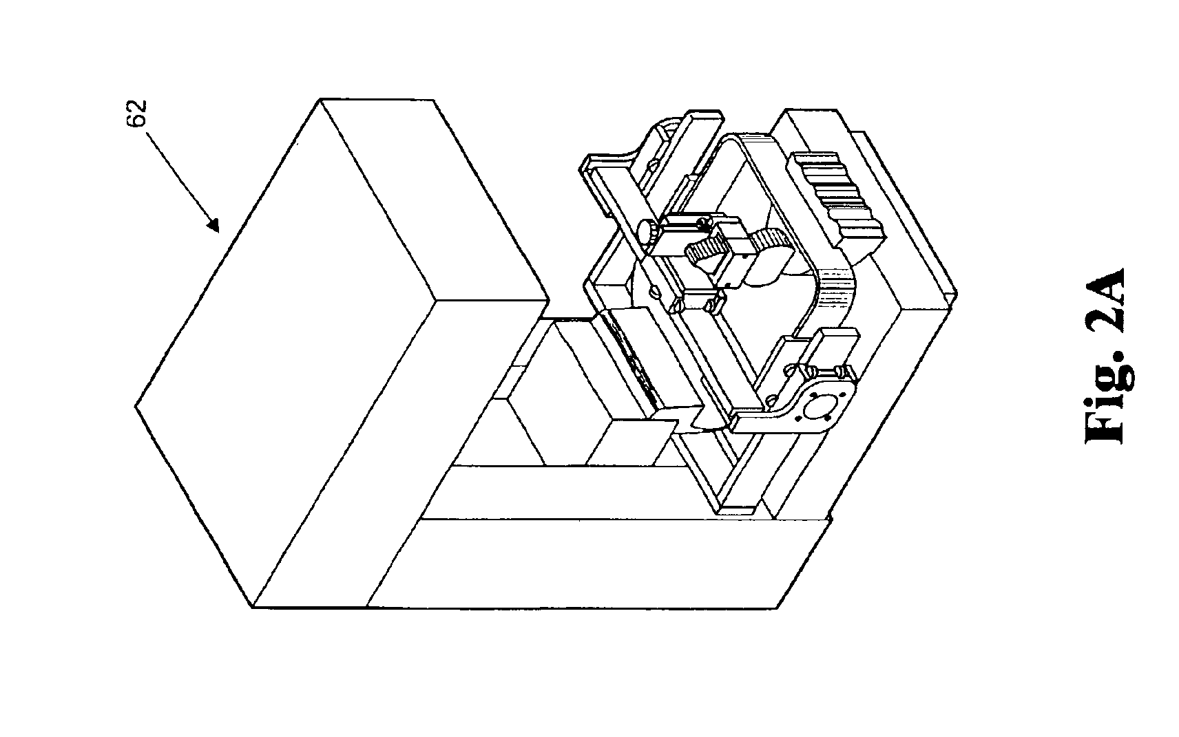
A three-dimensional mechanical scanner 20 carries an x-ray mammography compression paddle assembly 22, which is, in turn, inserted into an x-ray mammography unit 24 such as, for example, a Lorad x-ray mammography machine. A computer control system 26 drives the motion systems of mechani...


PUM


Abstract

A system for generating a three-dimensional image of the compressed breast 40 of a subject includes an x-ray mammography unit 24 for generating x-ray mammography data, a mechanical scanner 20 including an x-ray mammography compression paddle assembly 22, a control and motion system 26, 28 for driving the mechanical scanner 20 and for sensing the control and motion system's position, an ultrasound probe 32 for generating ultrasound image data in spatial registration with the x-ray mammography unit 24, and a computer 38 for generating from the ultrasound image data and the x-ray mammography data the three-dimensional ultrasound image. A method of examining a breast of a subject includes contacting an anterior surface of the breast with a compression paddle, applying pressure to the anterior surface of the breast with the compression paddle to compress it to reduce the thickness of the breast tissue, passing an ultrasound beam having a frequency greater than 3 MHz, preferably about 5 MHZ or more, through the paddle and the compressed breast tissue, receiving echoes from the compressed breast tissue through the compression paddle, and converting the echoes into breast examination data.

Description

FIELD OF THE INVENTIONThis invention relates to mammography methods and to apparatus for carrying out such methods.BACKGROUND OF THE INVENTIONCurrently, on an international scale, ultrasound breast examination is an accepted medical modality applied both as a primary method for evaluation of the breasts of young patients, that is, those under 40 years of age, and as an adjunct to x-ray mammography. See, for example, Kasumi, F., et al., “Topics in Breast Ultrasound,” Seventh International Congress on the Ultrasonic Examination of the Breast, Shinohara Publications, Inc., 1-7, Hongo 2-chome, Bunkyo-ku, Tokyo 113, Japan, 1991; Tohno, E., et al., Ultrasound Diagnosis of Breast Diseases, New York, Churchill-Livingstone, 1994; and, Stavros, A. T., et al., “Solid Breast Nodules: Use of Sonography to Distinguish Between Benign and Malignant Lesions,” Radiology 196, pp. 123-134, 1995. In terms of the diagnostic effectiveness of the ultrasound breast imaging, a number of investigators from th...

Claims


Application Information

Patent Timeline
IPC IPC(8): A61B6/04A61B8/08
CPCA61B6/0414A61B6/502A61B6/4417A61B8/0825Y10S128/915Y10S128/916A61B8/4245A61B8/483
Inventor DINES, KRIS A.KELLY-FRY, ELIZABETHROMILLY, ADA PATRICIA
Owner XDATA CORP
Learn More