Measurement of curvature of a subsurface borehole, and use of such measurement in directional drilling

a technology of subsurface borehole and measurement of curvature, which is applied in the direction of borehole/well accessories, instruments, surveys, etc., can solve the problems of reducing the gain or sensitivity which can be used in the system, adversely affecting the stability of the loop, and the typical direction measurement is subject to variable errors or noise, so as to reduce or minimize the difference between the measured and desired curvature, reduce or minimize the difference between the vector differen

Inactive Publication Date: 2005-04-12
SCHLUMBERGER WCP
View PDF31 Cites 22 Cited by
  • Summary
  • Abstract
  • Description
  • Claims
  • Application Information

AI Technical Summary

Benefits of technology

By contrast, according to the present invention, the bias signals are produced by measuring the curvature of the borehole, comparing the measured curvature with a desired curvature, and sending to the bias unit bias signals to reduce or minimize the difference between the measured and desired curvatures of the borehole.
As previously described, the actual curvature vector of the borehole can be measured, and in preferred embodiments can be measured in the vicinity of the drill bit and bias unit itself. Accordingly, the measurement of curvature can be more accurate and reliable than the measurement of direction in the prior art arrangements. As a result it becomes less necessary to average readings over time intervals, thus avoiding the difficulties previously referred to. Also, measurement of the curvature vector improves the stability of the control loop, since the phase of a curvature signal is 90° in advance of that of a directional signal.
The desired curvature may be determined and updated by measuring the direction of the borehole, comparing the measured direction with a desired direction, and determining the desired curvature which would reduce or minimize the difference between the measured and desired directions of the borehole.

Problems solved by technology

Typical direction measurements are subject to variable errors or “noise” due, for example, to vibration of the drill collar in the hole, magnetic disturbances, temperature fluctuations, servo and other instrument errors etc.
Unfortunately, such averaging necessarily causes delay and phase lag in the control loop, adversely affecting stability of the loop and reducing the gain or sensitivity which can be used in the system.
Any attempt to correct the phase lag by phase advance of the directional signals merely brings back the noise.
Although stabilizing filters can be optimized, accuracy and performance are still limited by signal noise.
Another possible cause of error is that the direction which is being measured may be the direction of the downhole hardware, and not the direction of the actual borehole itself.
The hardware may be inclined with respect to the borehole so that the measured direction is inaccurate.
Another problem is that, when calculating borehole direction, the relevant independent variable is not time, but is the incremental depth along the borehole, that is to say the required direction of a portion of the borehole depends on the location / depth of that part of the borehole and not on time.
Although the depth of the borehole generally increases with time, the rate of increase may not be constant.
Unfortunately, in most prior art systems information as to the depth of the borehole and the location of the bottom of the borehole is not available downhole.

Method used


Image

  • Measurement of curvature of a subsurface borehole, and use of such measurement in directional drilling
  • Measurement of curvature of a subsurface borehole, and use of such measurement in directional drilling
  • Measurement of curvature of a subsurface borehole, and use of such measurement in directional drilling

Examples


Embodiment Construction

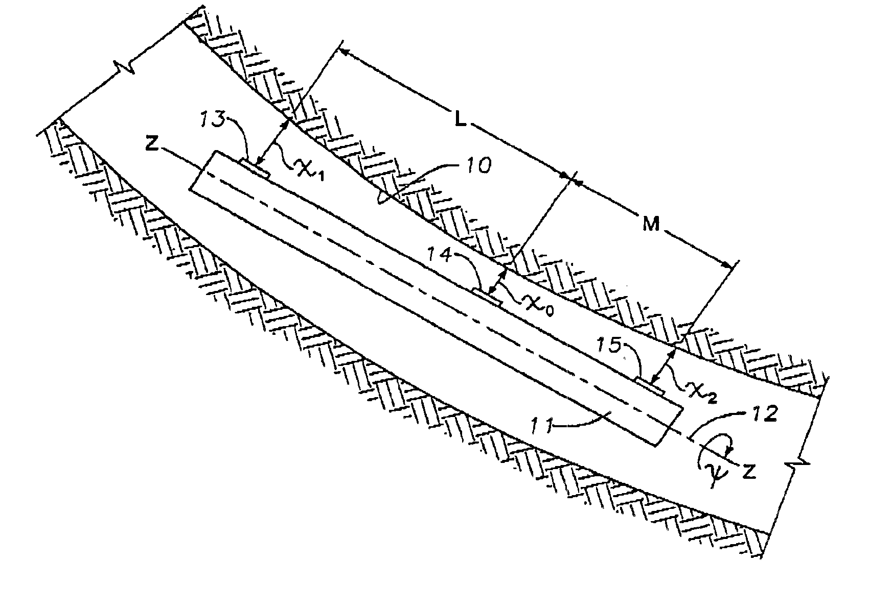
Referring to FIG. 1, there is shown a curved section of a subsurface borehole 10 in which is located an elongate structure 11 forming part of a downhole assembly. As will be described, the structure 11 may comprise part of a directional drilling downhole assembly but the invention is not limited to this application and the structure 11 may be part of any other form of downhole assembly.

The structure 11 may comprise a tubular drill collar which may be non-rotatable, in the case where the drill bit is rotated by a downhole motor, but preferably the structure 11 is rotatable about an axis 12 which extends longitudinally of the borehole 10.

Three distance sensors 13, 14 and 15 are fixedly mounted on the structure 11 and spaced apart along the length thereof. The sensors 13 and 14 are separated by a longitudinal distance L and the sensors 14 and 15 are separated by a longitudinal distance M. All three sensors lie along a line extending parallel to the axis of rotation 12 of the structure ...


PUM


Abstract

The present invention provides methods of measuring downhole the curvature of a borehole and, in a particular application of the invention, using the curvature information as an input component of a bias signal for controlling operation of a downhole bias unit in a directional drilling assembly.

Description

BACKGROUND OF INVENTION1. Field of the InventionIn directional drilling of subsurface boreholes, the downhole drilling assembly which incorporates the drill bit may also incorporate a bias unit which controls operation of the drilling assembly, in response to an input bias signal, to control the direction of drilling. As is well known, the drill string on which the drilling assembly is mounted may be rotated from the surface or the drill bit may be rotated by a downhole motor incorporated in the bottom hole assembly, in which case the drill string is non-rotating.2. Description of the Related ArtOne form of bias unit for controlling the direction of drilling in a rotary drilling system is disclosed in British Patent No. 2259316.In prior art directional drilling equipment, the direction (i.e. the inclination and azimuth) of a drill collar close to the drill bit is measured. The measured direction is compared at intervals or continuously with a desired direction (which may be input by...

Claims


Application Information

Patent Timeline
Patent Type & Authority Patents(United States)
IPC IPC(8): E21B47/022E21B47/02
CPCE21B47/02208E21B47/022E21B47/0224
Inventor BARR, JOHN D.DOWNTON, GEOFF
Owner SCHLUMBERGER WCP
Why Eureka
Try Eureka