
Self-contained temperature-change container assemblies

a container and self-contained technology, applied in the field of containers and equipment, can solve the problems of prone to leakage of steam or heated reactants from the reagent mixture of the device, and the device is prone to leaking either steam or heated reactants from the reagent mixture, and achieves the effect of large surface area and efficient thermal conductor

Inactive Publication Date: 2005-04-12
SELF HEATING TECH CORP
View PDF6 Cites 82 Cited by
  • Summary
  • Abstract
  • Description
  • Claims
  • Application Information

AI Technical Summary

Benefits of technology

"The invention is a self-contained container assembly that can heat or cool a product inside it. The assembly includes an outer jacket with two internal volumes containing temperature-change reagents. The reagents can mix through a reagent separator to initiate a chemical reaction that produces heat or cooling. The assembly also includes a movable member with penetrators to create openings through the reagent separator. The first reagent is calcium oxide and the second reagent is liquid water, which generates heat when mixed. The assembly can be used with standard size cans, allowing for easy inclusion in food or beverage manufacturing processes."

Problems solved by technology

The prior art devices suffer from various deficiencies, though.
Some of the devices are prone to leak either steam or heated reactants from the reagent mixture.
These devices can be hazardous in use.
Concern over the possible injuries to users has severely hindered the acceptability of these devices in the marketplace.
Other devices do not adequately control the rate of the reaction after its initiation.
The reaction may proceed either too fast or too slow, and too much or too little heat may be transferred to the food.
Other devices are overly complex, and difficult, expensive, or time-consuming to manufacture, assemble, use and dispose of.
For these reasons and others, there has never been an acceptable mass-market, self-heating product until now.

Method used


Image

  • Self-contained temperature-change container assemblies
  • Self-contained temperature-change container assemblies
  • Self-contained temperature-change container assemblies

Examples


Embodiment Construction

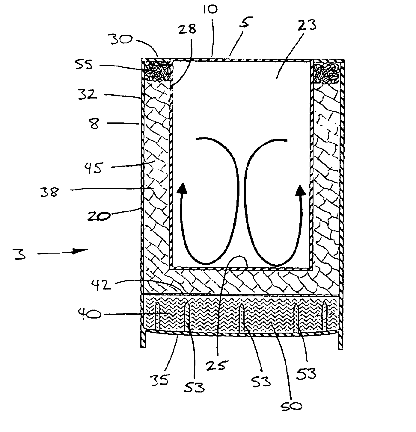
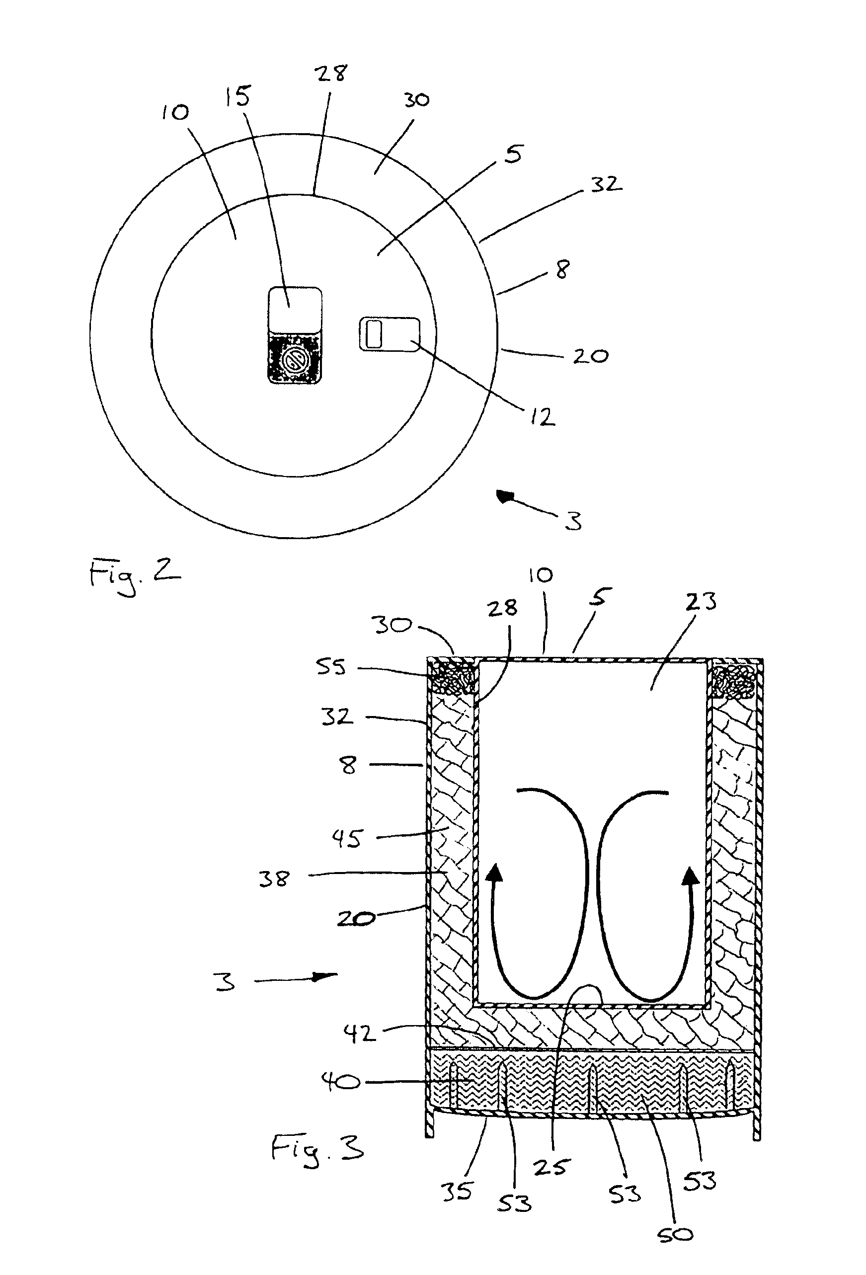
An exemplary embodiment of the invention is a self-contained temperature-change container assembly that is assembled around a standard food can or a similar container that holds a food product or another item that will be heated or cooled inside the container.

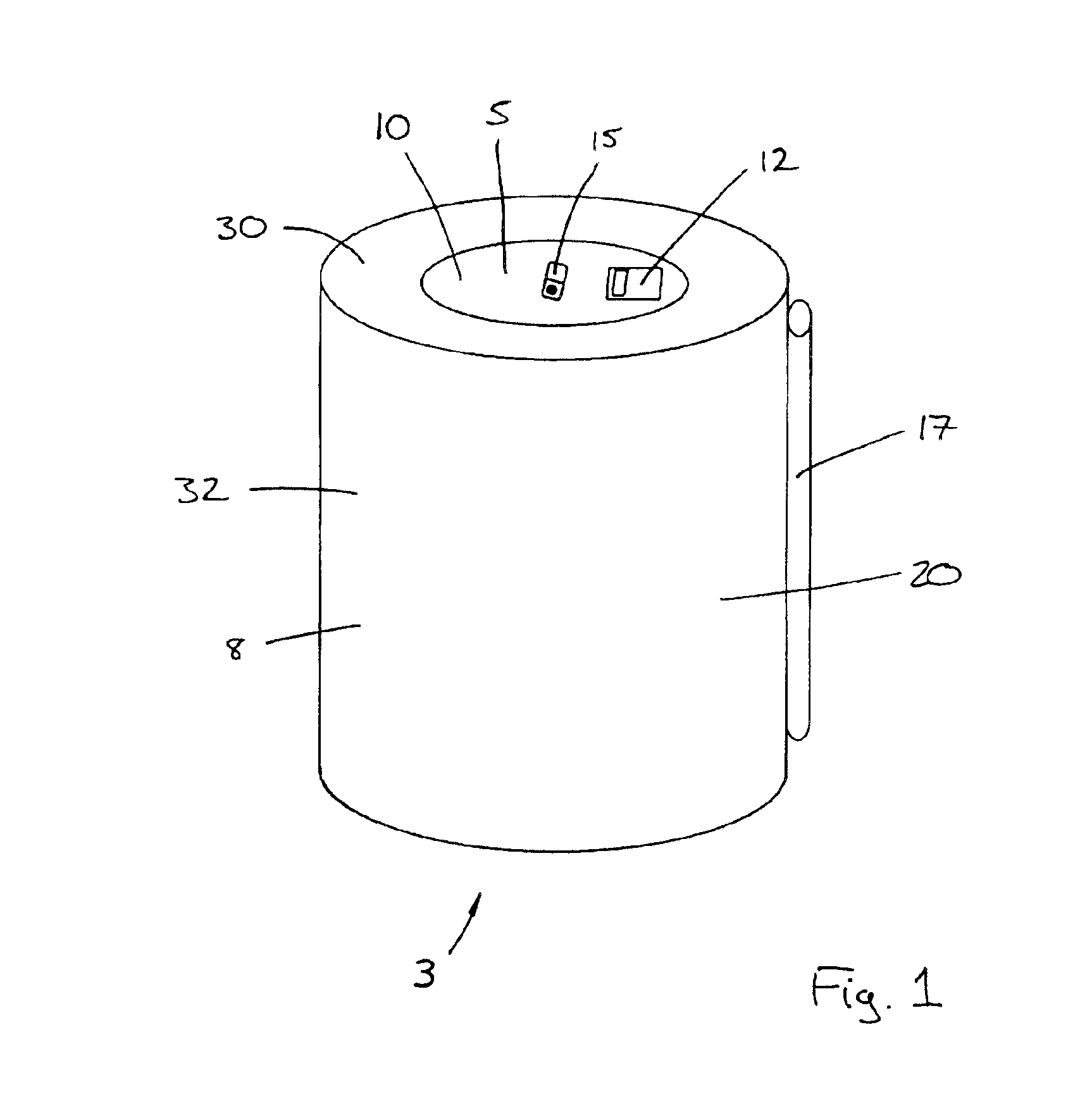
FIG. 1 is a perspective view illustrating a container assembly 3 embodying the invention. The container assembly is assembled around an inner container 5—in this embodiment, a cylindrical metal can that holds a quantity of a food or beverage.

The inner container 5 is partially enclosed inside an outer jacket 8, with the top 10 of the inner container exposed. A user can remove or open the can's top using a pull-tab opener 12, a mechanical can opener (not shown), or other conventional means.

A visual indicator 15 is provided on the top 10 of the can 5 or elsewhere in a suitable location. This indicator's color or appearance changes to signal that the can's top 10 (and by implication the food or beverage inside) has reached a desire...


PUM


Abstract

A container assembly heats or cools a product inside an inner container. An outer jacket at least partially surrounds the inner container, with a first internal volume and a second internal volume in the space between the outer jacket and the inner container. A first temperature-change reagent is contained inside the first internal volume, and a second temperature-change reagent is held in the second internal volume, with a reagent separator between the two. Several penetrators are disposed to penetrate the reagent separator to produce openings through the separator and through which the two reagents can mix. Steel wool inside the first internal volume acts as a steam condenser. The outer jacket includes a jacket top ring secured around an upper surface of a standard can, a jacket body secured to the jacket top, and a flexible jacket bottom that carries several spikes molded onto the jacket bottom.

Description

BACKGROUND OF THE INVENTIONThe invention relates generally to containers and apparatus for heating or cooling materials held inside containers. More particularly, the invention provides a can or a similar container for holding a food product or another material, and a self-contained assembly for heating or cooling the container and the material within it to a temperature above or below the material's storage temperature. In a preferred embodiment, a standard metal can holds a quantity of a food or beverage. A jacket or housing surrounds the can, with reagents for an exothermic or endothermic temperature-change reaction inside the jacket in proximity to the can. Activating the device initiates the reaction to heat or cool the can and its contents.Devices of this general type are known in the art. Some such devices include a food container in proximity to a reagent storage vessel. The reagent storage vessel holds a quantity of calcium oxide and a quantity of water, with a barrier betw...

Claims


Application Information

Patent Timeline
Patent Type & Authority Patents(United States)
IPC IPC(8): A47J27/02A47J27/022A47J36/28A47J27/00A47J36/24F25D5/02F24J1/00F25D5/00F24V30/00
CPCA47J27/002A47J27/022F24J1/00F25D5/02A47J36/28F25D2400/36F24V30/00
Inventor SCHREFF, H. JOSHUARIZZI, MASSIMILIANO
Owner SELF HEATING TECH CORP
Learn More